
Free course2026 edition17 modules
From your first zone circuit to commissioning a full addressable network. Learning objectives, worked examples with real numbers, site mistakes I see every month, a step-by-step termination guide and a short quiz at the end of every module.
When I started in ELV work, nobody sat me down and explained a fire alarm system from the beginning. I learned it the hard way: on ladders, reading panel manuals at midnight and fixing faults other people left behind. This fire alarm course is the study guide I wish I had back then. It starts at zero, with what a detector actually does, and walks you through circuits, loops, sounders, power, cause and effect, interfaces, termination and testing until you can read a design, install it properly and hand it over with confidence.
Quick answer: A fire alarm system has three jobs: detect (detectors, call points, sprinkler switches), decide (the control panel watches every circuit and follows a programmed cause and effect), and warn and act (sounders, strobes, voice messages, and signals that stop fans, recall lifts and release doors). Every wire that matters is supervised, so the panel reports a fault before a fire ever needs that wire. Learn the circuits first, then detection and notification, then power, interfaces and testing. That is exactly the order of this guide.
This guide gives general, practical guidance for learning. It is not a design standard and it does not replace one. In Saudi Arabia, the Saudi Fire Protection Code (SBC 801, Section 907) calls for fire alarm systems to be installed in line with NFPA 72, and NFPA lists the 2025 edition of NFPA 72 as the current edition. Many GCC projects instead follow British and European practice: BS 5839-1 for design and installation with BS EN 54 products. Always check which edition your project specification names and what the local authority (Civil Defense in KSA) accepts, and follow the equipment manufacturer’s instructions. Where I give numbers, treat them as typical learning values and confirm them against the current documents.
How to Use This Fire Alarm Course
Read the modules in order the first time. Each one opens with what you will be able to do at the end, explains the idea in plain words, shows a worked example where numbers matter, lists the mistakes I keep finding on site, and closes with a key takeaway and a quick quiz. Open the quiz only after you have tried to answer in your head. If you get two out of three, move on. If not, read the module again; it is faster than relearning on a live job.
If you already work in the trade, jump straight to the parts you need: battery and voltage-drop maths in Modules 12 and 5, the cause and effect matrix in Module 13, or the termination steps in Module 15. When you want to practise, the free Fire Alarm Design Tool and the Conventional Fire Alarm Design Tool let you lay out devices on a floor plan and see the loop and zone counts as you go.
MODULE 1How a Fire Alarm System Works
- Describe a fire alarm system as inputs, processing and outputs.
- Name the three signal families a panel reports: alarm, supervisory and trouble (fault).
- Explain why the system has two power sources.
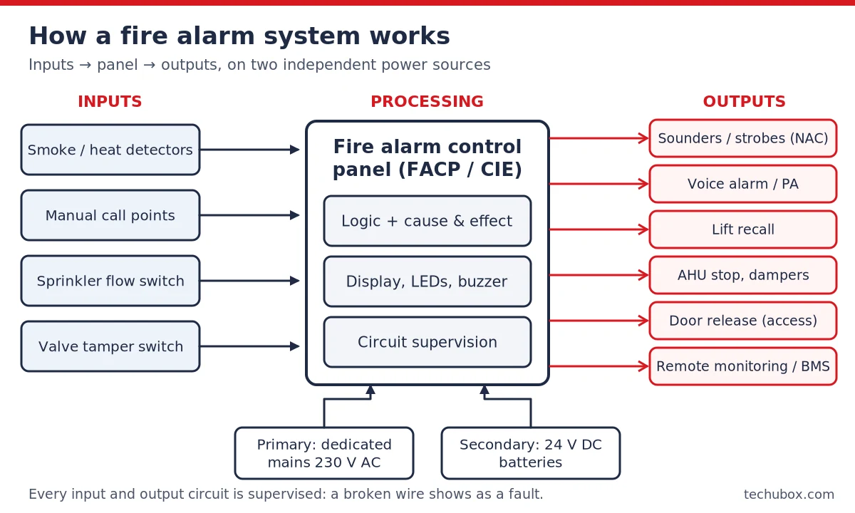
Forget the brand names for a moment. Every fire alarm system I have ever worked on, from a two-zone villa panel to a networked hospital, is built on the same simple idea: something senses, something decides and something responds.
Inputs are the things that tell the panel what is happening. Smoke and heat detectors sense a fire on their own. Manual call points (pull stations in American terms) let a person raise the alarm. Sprinkler flow switches report that water is moving in the pipes, and valve tamper switches report that somebody has closed a valve they should not have touched.
Processing happens in the fire alarm control panel, often written FACP or CIE (control and indicating equipment). The panel watches its circuits all day and night. When an input changes, it checks its programming and decides what to do next.
Outputs are what the panel makes happen: sounders and strobes to warn people, voice messages in bigger buildings, a signal to the monitoring centre or the fire brigade, and control signals that shut down air handling units, close smoke dampers, bring lifts to the exit floor and unlock escape doors.
Three kinds of signal
A good panel never just says “something happened”. It sorts every event into a family, and each family gets its own sound, light and response:
| Signal | What it means | Typical example | Typical response |
|---|---|---|---|
| Alarm (fire) | A fire may be happening | Smoke detector or call point operates | Sounders, strobes, fire brigade call, fan and lift actions |
| Supervisory | A fire protection system is not ready | Sprinkler valve closed, fire pump fault | Distinct buzzer at panel, message to the facility team |
| Trouble / fault | The fire alarm itself has a problem | Broken wire, earth fault, battery missing | Fault buzzer and LED, technician call-out |
British documents usually group things as “fire” and “fault”, and many panels add a “pre-alarm” for analogue detectors that are rising towards alarm. The idea is the same: the person reading the panel must know at a glance whether to evacuate, whether to send a sprinkler fitter, or whether to call the fire alarm technician.
Why two power sources
Fire can take out the building’s normal supply, and a site electrician can trip the wrong breaker on a quiet Tuesday. So a fire alarm panel has a primary supply, usually a dedicated, labelled mains circuit, and a secondary supply, usually sealed lead-acid batteries. The panel charges the batteries, watches them, and reports a fault when either source disappears. We size those batteries in Module 12.
- Feeding the panel from a general socket circuit instead of a dedicated, locked and labelled supply.
- Treating supervisory and trouble signals as “the panel beeping again” and silencing them for weeks.
- Leaving the panel in a back room where nobody hears the fault buzzer.
Inputs, processing, outputs, all running on two independent supplies, with every important wire watched. If you can draw the block diagram from memory, you already understand the backbone of every system in this course.
Module 1 quiz (tap to open)
- A sprinkler control valve is closed during maintenance. Which signal family should the panel show?Supervisory. The fire protection system is impaired, but nothing is burning and the alarm wiring is fine.
- Name two outputs other than sounders.Any two of: strobes, voice messages, remote monitoring signal, AHU shutdown, damper control, lift recall, door release.
- Why is a battery fault reported as a trouble signal?Because the system has lost its secondary supply and might not survive a mains failure, so someone must fix it.
MODULE 2Devices, Appliances and the Words You Must Know
- Tell an initiating device from a notification appliance.
- Use the core vocabulary correctly on drawings and in meetings.
- Match American and British terms for the same equipment.
Half the arguments I hear on site come from people using different words for the same thing. Getting the vocabulary right saves a surprising amount of time, especially on GCC projects where the consultant writes in NFPA language, the supplier’s manuals are written to EN 54, and the installer learned the trade on a British-style job.
The cleanest split is this: devices tell the panel something, and appliances tell people something. An initiating device starts a signal. A notification appliance delivers a warning. A smoke detector is a device; a horn-strobe is an appliance. A monitor module is a device too, because it reports an input. A control module is neither: it is an output that drives other equipment.
| Term (NFPA style) | Common British / EN term | Plain meaning |
|---|---|---|
| Fire alarm control unit (FACU / FACP) | Control and indicating equipment (CIE) | The panel |
| Initiating device | Detector, manual call point, input device | Anything that starts a signal |
| Manual fire alarm box / pull station | Manual call point (MCP), break glass | The red box people operate by hand |
| Notification appliance | Sounder, beacon, visual alarm device (VAD) | Anything that warns people |
| Initiating device circuit (IDC) | Detection zone circuit | Conventional input wiring |
| Signaling line circuit (SLC) | Addressable loop | Data plus power to addressable devices |
| Notification appliance circuit (NAC) | Sounder circuit | Wiring that powers sounders and strobes |
| Authority having jurisdiction (AHJ) | Enforcing authority, approving body | Civil Defense in KSA; the people who sign you off |
| Trouble signal | Fault signal | The system itself has a problem |
A few more words you will meet everywhere in this guide. Supervision (or monitoring for integrity) means the panel constantly checks that a circuit is intact. An EOL is the end-of-line device, usually a resistor, that makes supervision possible on conventional circuits. A zone is an area of the building that the panel reports as one place. Cause and effect is the written rule for what each input makes happen. Listed or approved means a test laboratory has examined the product for that use; NFPA projects usually ask for UL or FM listings, and BS projects usually ask for EN 54 certification by a third-party body.
- Calling every red box on the wall a “detector” in reports, so nobody knows what failed.
- Mixing devices from two manufacturers on one loop because “the protocol looks the same”. Compatibility must be confirmed in the manufacturer’s documents.
- Writing “zone 3 fault” in the logbook without the location. Zones mean nothing without a zone chart.
Devices talk to the panel, appliances talk to people, modules connect the system to other equipment. Learn both sets of names and you can work comfortably on NFPA and BS projects alike.
Module 2 quiz (tap to open)
- Is a strobe light an initiating device or a notification appliance?A notification appliance. It warns people; it does not start a signal.
- What is the British name for an SLC?An addressable loop.
- Who is the AHJ for a fire alarm system in Riyadh?The Civil Defense, through its approval and inspection process.
MODULE 3Zones, IDCs, EOL Resistors and Supervision
- Explain how a conventional zone tells normal, alarm and fault apart.
- Calculate the quiet current through an end-of-line resistor.
- Recognise open, short and earth (ground) faults and what each one does.
A conventional zone circuit is a pair of wires that leaves the panel, visits every detector and call point in one area, and finishes at an end-of-line resistor. The panel puts a voltage across the pair, typically around 24 V DC, and measures the current that flows. That single measurement is all it has, and it is enough.
In the normal state, the only path for current is the EOL resistor, so a small, steady current flows. The panel learns that value and calls it healthy. If a wire breaks anywhere, the EOL is cut off, the current falls to almost nothing, and the panel reports an open-circuit fault. When a detector operates, it switches a low resistance (often a few hundred ohms, built into the detector or base) across the pair. The current jumps well above normal, and the panel reports a fire on that zone.
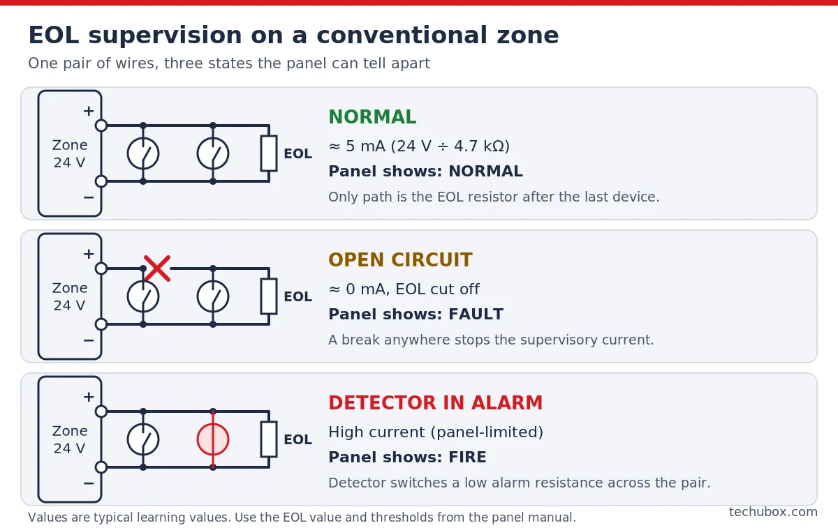
A zone runs at 24 V DC and the panel maker supplies a 4.7 kΩ end-of-line resistor. Ignoring the small cable resistance, Ohm’s law gives the supervisory current:
I = V ÷ R = 24 ÷ 4,700 = 0.0051 A, about 5.1 mA.
Now a detector operates and switches a 470 Ω alarm resistor across the line. That resistor sits in parallel with the EOL, so the combined resistance is about 427 Ω and the current wants to rise above 50 mA. In practice, the panel limits the zone current, but it is far above the 5 mA “normal” band, so the panel calls it a fire. Cut the cable and the reading drops towards 0 mA: a fault. Three clearly separated current bands, three different messages.
Two practical notes. First, the EOL value belongs to the panel, not to the installer’s spare parts box. A 4.7 kΩ resistor on a panel designed for 6.8 kΩ may give a zone that never settles. Second, how a panel treats a hard short (almost zero ohms) varies. Some older and NFPA-style designs read it as an alarm, which is why technicians sometimes test a zone by bridging it. Many modern panels, particularly EN 54 types, report a dead short as a short-circuit fault and only accept the detector’s resistance band as a fire. Read the panel manual before you bridge anything.
Earth (ground) faults
The third fault family is less obvious. If a conductor touches a metal tray, a conduit or a wet ceiling grid, there is now an unintended path to earth. One earth fault might not stop the zone working, but a second one on another conductor could create a false alarm or kill a circuit. That is why panels watch for leakage to earth and report it as a fault on its own. Earth faults are the ones that waste the most commissioning time, because the panel can usually tell you that one exists but not where. Good cable handling and insulation testing before you connect the panel are your best defence; see Module 15.
Zoning rules worth knowing
A zone is a search area for the fire team, so it must make sense on the ground. British practice limits a zone to one floor in most cases, to roughly 2,000 m² of floor area, and to a search distance that someone can cover quickly, commonly quoted as 60 m. NFPA projects tie zoning to the building code and the AHJ, and NFPA 72 sets separate limits on how many waterflow and supervisory switches you may put on one conventional circuit. Keep alarm devices and supervisory devices (valve tamper switches, for example) on separate circuits or separate addresses so the panel can show the right signal family.
- Fitting the EOL resistor inside the panel “to keep it neat”. The panel then supervises nothing beyond its own terminals.
- Looping both cables under one terminal screw so that removing a detector does not break the circuit. Supervision must see a removed device.
- Teeing a spur off a conventional zone. The spur has no EOL, so a break on it goes unseen.
- Using whatever resistor is in the bag instead of the value the panel maker specifies.
A conventional zone is a current meter with three bands: low means open, normal means healthy, high means fire. The EOL resistor at the far end is what makes the whole trick work, so it must always be the last thing on the line.
Module 3 quiz (tap to open)
- A zone at 24 V uses a 6.8 kΩ EOL. What is the approximate quiet current?24 ÷ 6,800 ≈ 3.5 mA.
- An installer fits the EOL at the panel terminals. What fault will the panel fail to see?An open circuit anywhere along the field wiring, because the EOL is still connected and current still flows.
- Why are tamper switches kept apart from smoke detectors on conventional circuits?So the panel can report a closed valve as a supervisory signal instead of a fire alarm.
MODULE 4Conventional vs Addressable, SLC Loops and Modules
- Explain how an addressable loop polls devices and why it is not judged by current alone.
- Place short-circuit isolators so one fault removes only a small part of the loop.
- Choose between a monitor module and a control module for a given job.
On a conventional zone, the panel knows that one of the devices on a pair of wires has operated, but not which one. That is fine for a small shop. In a tower with 3,000 devices, “fire, zone 14” sends the team running around a whole floor. Addressable systems fix this by giving every device its own number.
The wiring that carries those numbers is the signaling line circuit (SLC), better known on site as the loop. The panel sends a query down the loop to one address at a time and that device answers with its status. Analogue addressable detectors go further: instead of answering “normal” or “fire”, they send a value that represents how much smoke or heat they see. The panel then decides when that value counts as pre-alarm, fire or “dirty, please clean me”. It also lets you set different sensitivities for day and night, or for a kitchen corridor versus an office.
Because the loop is a data circuit, it supervises itself through communication. If a device stops answering, the panel reports that address as missing. That is why an addressable loop does not need an EOL resistor the way a conventional zone does.
| Point | Conventional | Addressable |
|---|---|---|
| Location shown | Zone only | Exact device and text label |
| Wiring | One circuit per zone, radial to EOL | One loop for many zones, often returned to panel |
| Supervision | Current through EOL | Communication with every address |
| Cause and effect | Per zone | Per device, per group, per time of day |
| Maintenance data | Very little | Drift, contamination and sensitivity reports |
| Typical fit | Villas, small shops, small warehouses | Offices, hotels, hospitals, malls, towers |
If you want a deeper comparison of cost and design, I wrote one here: Addressable vs Conventional Fire Alarm Systems.
Short-circuit isolators
A loop carries a lot of the building on one cable, so one short circuit must not kill the lot. Isolators are small switches, either built into device bases and modules or fitted as separate units, that open automatically when they sense a short on their side. On a loop that returns to the panel, the panel then feeds both ends, and only the short section between two isolators goes dark.
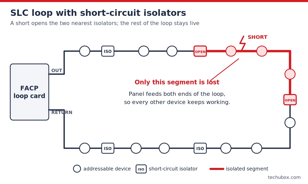
How many devices between isolators? Follow the panel maker and the specification. In European practice, 32 devices is a figure you will see often, and many designers go further and put an isolator at every zone boundary and every floor crossing, so a fault never spreads beyond one zone. NFPA 72 sets its own rules on how much of a circuit a single fault may affect, depending on the circuit class; check the current edition. Whatever the number, keep the loop within the manufacturer’s limits for device count, cable length, resistance and capacitance.
A four-storey office has 46 smoke detectors, 8 call points, 6 sounder bases and 4 modules per floor, so 64 addresses per floor and 256 in total. The panel maker allows 250 addresses per loop and recommends no more than 32 devices between isolators.
Step 1: 256 addresses is more than 250, and you always want spare capacity for changes. Use two loops, floors 1 and 2 on loop 1 (128 addresses) and floors 3 and 4 on loop 2. That leaves roughly half of each loop free, which is comfortable.
Step 2: each floor has 64 devices, so put an isolator where the loop enters the floor, one in the middle and one where it leaves. No segment then exceeds 32 devices, and no fault crosses a floor.
Step 3: run the loop out and back by different routes where you can, so a single damaged tray does not cut both legs.
Monitor modules and control modules
Not everything in a building speaks your panel’s protocol. A sprinkler flow switch is just a contact; so is a fire pump “running” signal or a kitchen hood suppression system. A monitor module (also called an input module or interface) gives such a contact an address on the loop. Its input is usually supervised with its own EOL at the far end, so the panel sees a cut wire between the module and the switch.
A control module (output or relay module) does the opposite: on command from the panel, it changes a relay contact or switches a supervised output. That contact may stop an AHU, release a door, close a damper or signal a lift controller. Some control modules switch a supervised 24 V output with external power, which suits door holders and sounder groups. Dual and multi-channel modules combine inputs and outputs in one box, handy for dampers where you want to close the damper and confirm it actually closed.
- Running the loop out and back in the same tray, so one cut opens both legs.
- Duplicate addresses after a device swap. Two devices answering one address can cause random faults that are hard to trace.
- Labelling devices “Detector 1-045” in software instead of a location that a guard can find at 3 a.m.
- Using a monitor module for a fan control output, or a control module to read a contact.
Addressable loops buy you exact location and per-device logic. Isolators decide how much of that loop survives a short, and modules connect the loop to everything that is not a detector.
Module 4 quiz (tap to open)
- Why does an addressable loop not need a conventional EOL resistor?The panel supervises it by talking to every address; a device that stops answering is reported missing.
- A short happens between isolators 3 and 4 on a returned loop. What is lost?Only the devices between those two isolators; the rest are fed from both ends.
- Which module do you need to report a fire pump running signal?A monitor (input) module.
MODULE 5Notification Appliance Circuits (NAC) and Voltage Drop
- Explain how polarity reversal lets one pair of wires be both supervised and powered.
- Work out the voltage at the last sounder with a voltage-drop calculation.
- Know why strobes must be synchronised.
A notification appliance circuit (NAC), or sounder circuit, has a harder job than a detection zone. It must be watched for faults while it sits idle for years, and then deliver real power the moment there is a fire. Conventional panels solve this with reverse polarity supervision.
In the quiet state, the panel applies a small voltage with the polarity reversed. Every sounder and strobe has a diode (or equivalent electronics) that blocks current in that direction, so the appliances stay silent. The only path is the EOL resistor at the end, and the panel measures that tiny current just like a detection zone: too low means open, too high means short. On alarm, the panel flips the polarity and switches full power onto the pair. The diodes now conduct, the appliances operate, and the EOL just carries a little extra current.
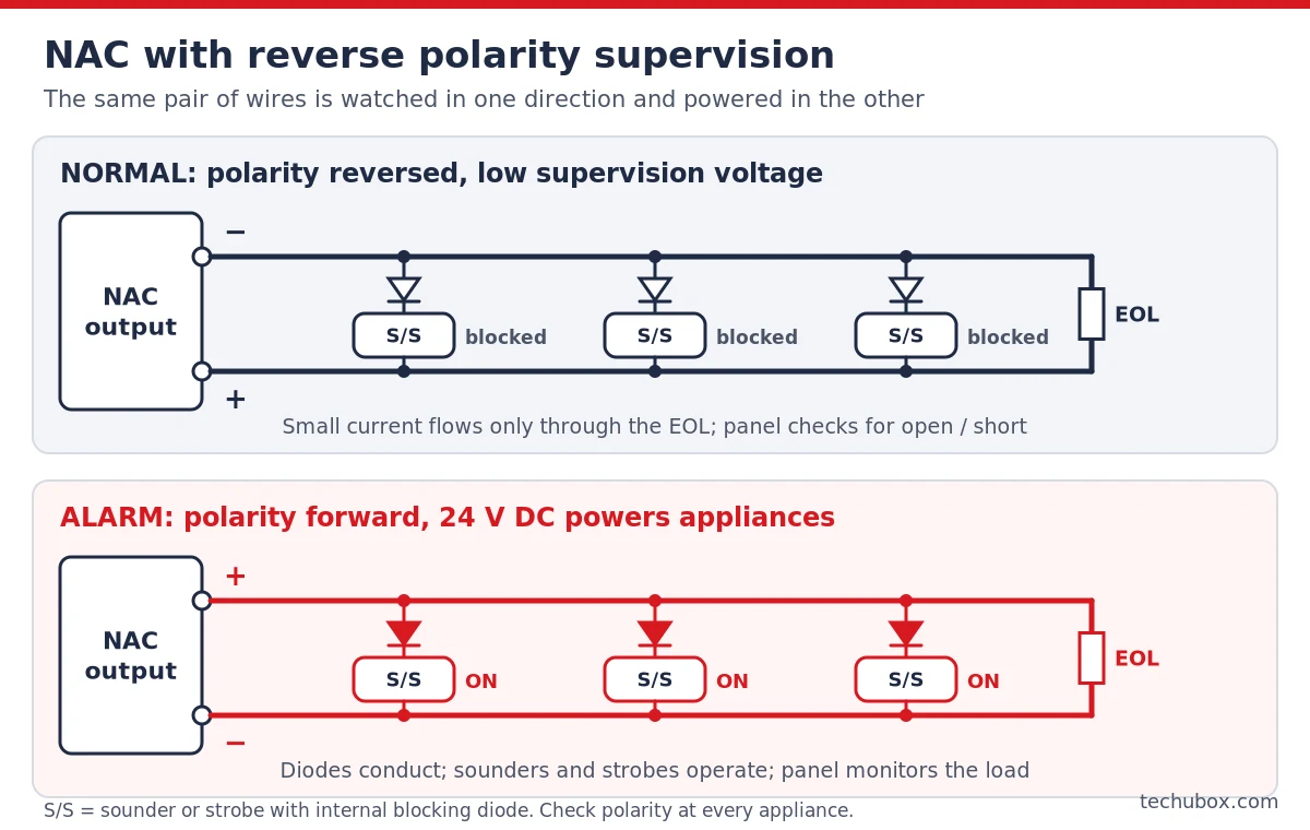
Because the circuit is polarised, every appliance has marked + and − terminals, and they must be wired the right way round. Get one backwards and that appliance either stays silent in alarm or, worse, conducts in the quiet state and makes the circuit read as a short. Addressable sounders and sounder bases change the picture: they live on the loop or on a dedicated addressable sounder circuit, and the panel can switch them in groups by software. In NFPA terms, such a circuit is both an SLC and a NAC, so it must meet the rules for both.
Synchronisation
When several strobes flash out of step in one field of view, the combined flash rate can rise into a range that may trigger photosensitive seizures. That is why visible appliances in one space must flash together. Strobes either carry their own sync protocol on the NAC, use a sync module, or rely on the panel or power extender to send the sync. Never mix strobes from different families on one circuit unless the manufacturer says they synchronise together. Many horn-strobes also let the horn be silenced while the strobes keep flashing.
Voltage drop: the calculation every NAC needs
Appliances are listed to work over a voltage range. On a 24 V system, NFPA-style appliances are typically listed down to 16 V. Your panel output is not a steady 24 V either. On batteries near the end of their standby period, it can sag to roughly 20.4 V (1.7 V per cell × 12 cells for a 24 V lead-acid set), and that is the voltage I calculate from. The cable then drops more on the way. The last appliance must still get at least its minimum listed voltage.
A corridor NAC feeds 12 horn-strobes. Each draws 0.12 A at low voltage (use the worst-case current from the datasheet). Cable run to the last appliance: 120 m. To be safe, assume the whole load sits at the far end.
- Total current: 12 × 0.12 = 1.44 A.
- Loop length of conductor (out and back): 2 × 120 = 240 m = 0.24 km.
- With 1.5 mm² copper at about 12.1 Ω/km: R = 0.24 × 12.1 = 2.90 Ω.
- Voltage drop: V = I × R = 1.44 × 2.90 = 4.18 V.
- Voltage at the last strobe: 20.4 − 4.18 = 16.2 V. Only just above 16 V, with no margin for hot ceilings.
- Try 2.5 mm² at about 7.41 Ω/km: R = 1.78 Ω, drop = 2.56 V, end voltage = 17.8 V. Comfortable.
Hot climate check: copper resistance rises about 0.4% per °C. A ceiling void in a Riyadh summer can easily reach 50 °C, which is 30 °C above the 20 °C reference and adds roughly 12% to the resistance. On the 1.5 mm² option, that pushes the drop to about 4.7 V and the end voltage below 16 V. That is why I go up a cable size or split the circuit instead of designing to the edge.
You can run the same numbers in seconds with the Techubox Voltage Drop Calculator. Always use the appliance maker’s current at the lowest operating voltage, because strobes draw more current as the voltage falls.
- Calculating voltage drop from 24 V instead of the end-of-battery voltage.
- Adding strobes to an existing NAC at fit-out without redoing the calculation.
- Reversed polarity on one appliance, giving a short-circuit fault that “comes and goes”.
- T-tapping a conventional NAC to reach one extra room.
A NAC is supervised in reverse and powered forward. Design it for the worst day: low battery, hot ceiling, every appliance at its highest current. If the last appliance still gets its minimum voltage, you are good.
Module 5 quiz (tap to open)
- What stops sounders operating during reverse-polarity supervision?A blocking diode (or equivalent circuit) in each appliance.
- A NAC draws 2 A over 0.2 km of conductor loop at 7.41 Ω/km. What is the drop?R = 0.2 × 7.41 = 1.48 Ω; drop = 2 × 1.48 ≈ 2.96 V.
- Why must strobes in one room flash in sync?Unsynchronised flashes add up to a higher combined flash rate that can trigger photosensitive seizures.
MODULE 6Control Circuits and Emergency Control Functions
- Explain fail-safe control using a door holder as the example.
- Describe how a relay contact interfaces the panel to fans, dampers, lifts and doors.
- Know why a circuit used for control should not also carry appliances.
A fire alarm does more than make noise. In a modern building, it is the conductor of an orchestra: the panel tells other systems what to do in a fire. NFPA calls these emergency control functions, and British documents talk about fire alarm interfaces and ancillary equipment. Either way, the wiring that carries those commands is what I call a control circuit.
The fail-safe idea
Take a magnetic door holder on a corridor fire door. In normal use, the coil is energised and holds the door open. On alarm, the panel or a relay removes the power and the door closes under its own closer. The beauty of this arrangement is that it fails safe: if the cable is cut, the fuse blows or the supply fails, the magnet lets go and the door closes. A fault produces the same result as an alarm, so such a circuit is usually not required to be supervised in the same way as a sounder circuit. The door closes either way.
The opposite case, where something must be energised to act (a damper actuator that needs power to close, a solenoid that must pull in), cannot fail safe. If the cable breaks, the command never arrives and nobody knows. Such circuits need supervision, either by using a supervised output or by confirming the action with a feedback input.
Relays: the universal interface
Most interfaces end at a dry relay contact: NO (normally open), C (common) and NC (normally closed). The panel or a control module changes the relay; the other system’s own wiring goes through the contact. Typical uses:
| Function | Usual contact arrangement | Field note |
|---|---|---|
| AHU / fan shutdown | NC contact in the starter control circuit opens on alarm | Fire alarm relay at 24 V; never switch the motor power directly |
| Smoke damper close | Contact removes actuator power (spring return) or drives it closed | Use an end-switch input to confirm the damper really closed |
| Lift recall (homing) | Contact to the lift controller’s fire input, one per recall level where required | Lift maker decides voltage and logic; agree it in writing |
| Access-controlled door release | NC contact in series with the lock power so locks drop on alarm | Hard-wired, fail-safe locks on escape routes |
| Door holders | Power removed on alarm | Naturally fail-safe |
| Gas valve / kitchen supply cut | Contact to the shunt-trip or valve controller | Coordinate with MEP; confirm reset procedure |
For door release in detail, with wiring and test steps, see my guide on access control and fire alarm integration. For lifts, access control and elevator integration covers what happens to card readers in the car during recall.
Using a NAC as a control circuit
Sometimes a spare panel NAC drives relays, door holder supplies or NAC power extenders instead of sounders. That is fine, but once a NAC is designated as a control circuit, keep it for control only. If sounders shared that circuit, a fault on a door holder could disable warnings to occupants. The relay coils on such a circuit usually carry their own diodes, so the reverse-polarity supervision still works.
Addressable control modules do the same job from the loop. Remember that the module itself is supervised by the loop, but the wiring from its contact to the equipment it controls usually is not, unless you add feedback.
- Fire alarm relay wired to the NO contact for a fan stop, so a broken wire means the fan never stops.
- Switching 230 V motor loads through a small module relay rated for low-voltage signalling.
- No written agreement with the lift contractor on which floor is the recall floor and what happens if that floor is in alarm.
- Damper commands with no feedback, so commissioning cannot prove the damper moved.
Design control circuits so that a fault leads to the safe state. Where that is impossible, supervise the circuit or confirm the action with feedback. Keep control and notification on separate circuits.
Module 6 quiz (tap to open)
- Why is a door holder circuit called fail-safe?Losing power, for any reason, releases the door, which is the same result as an alarm.
- Which relay contact goes in series with a maglock’s power for fire release?The NC contact, which opens on alarm and drops the lock power.
- Name one way to prove a smoke damper actually closed.An end-switch or position feedback contact wired to a monitored input.
MODULE 7Externally Powered Devices and Power Supervision
- Tell two-wire devices from four-wire devices.
- Explain why an external power feed must be supervised.
- Wire an end-of-line power supervision relay correctly.
Most detectors take their power from the same two wires that carry their signal. These are two-wire devices. Some devices need more power than a zone or loop can provide: beam detectors, aspirating units, some flame detectors, duct detector housings with their own relays, and many conventional four-wire smoke detectors used with relays for local control. These take a separate 24 V DC feed, so they are called four-wire devices (although some need more conductors than that).
Here is the catch. If that separate power feed is lost, the device goes dead, but its signal circuit may still look perfectly healthy to the panel. Nobody would know the detector had stopped working. So the power circuit must be supervised too.
The classic fix is an end-of-line power supervision relay. Run the power pair to every four-wire device and finish it at a small relay coil after the last device. While power is present, the relay is energised. Now put that relay’s contact into the signal circuit:
- On a conventional zone, wire the relay’s normally open contact in series with the zone, just before the EOL resistor. With power on, the contact is closed and the zone reads normal. If power fails, the relay drops out, the contact opens, and the zone reports an open-circuit fault. The panel does not know whether the zone wiring or the power wiring failed, but it knows something needs attention.
- On an addressable loop, feed the relay contact into a monitor module and program that address as “auxiliary power fault, level 3 riser”. Now the panel tells you exactly what failed.
The relay must be electrically last on the power circuit; otherwise a break beyond it goes unseen. The same thinking applies to external power supplies feeding NAC extenders, door holder supplies and aspirating units: each should report mains failure, battery failure and output faults back to the main panel.
A car park has six four-wire smoke detectors with relays for local fan control. Each draws 25 mA in standby and 45 mA in alarm. The EOL relay draws 15 mA. Standby total: 6 × 25 + 15 = 165 mA. Alarm total, assuming all six operate: 6 × 45 + 15 = 285 mA. Those values go into the battery calculation (Module 12) of whichever power supply feeds them. Check voltage drop the same way as Module 5, using each device’s minimum operating voltage.
- Powering beam detectors from a non-fire-rated “spare” 24 V adaptor with no battery and no monitoring.
- Putting the supervision relay at the first device to save cable.
- Forgetting auxiliary loads in the battery calculation.
If a device needs its own power, that power is part of the fire alarm system. Supervise it, back it up with batteries, and include it in your calculations.
Module 7 quiz (tap to open)
- What happens on a conventional zone when the power to the EOL supervision relay fails?The relay contact opens, the zone sees an open circuit and reports a fault.
- Where must the supervision relay be connected on the power circuit?After the last powered device, so it is electrically last.
- Give two examples of devices that usually need external power.Any two of: beam detectors, aspirating detectors, some flame detectors, four-wire smoke detectors, some duct detector housings.
MODULE 8Circuit Classes A, B, C, D, E, X and Pathway Survivability
- Describe the six NFPA circuit classes in one sentence each.
- Explain why T-taps break Class B supervision on conventional circuits.
- Choose a survivability approach and the matching BS cable type.
NFPA 72 does not describe circuits by the number of wires. It describes them by what they still do when something goes wrong: an open, a short or a single earth fault. That performance is the “class” of the pathway.
| Class | In plain words | Typical use |
|---|---|---|
| A | Has a redundant return path; keeps working past a single open, and reports it | Loops and NACs in larger or critical buildings |
| B | No redundant path; a single open is reported, but devices beyond the break are lost | Most conventional zones and NACs |
| C | Supervised by end-to-end communication rather than by current; no redundant path | Ethernet or IP links between panels and annunciators |
| D | Not supervised, but designed so a fault leads to the intended safe action | Fail-safe door holder circuits |
| E | Not supervised for integrity | Non-critical auxiliary wiring |
| X | Redundant path that keeps working past a single open, a single short or an earth fault | Critical loops with isolators, networks between panels |
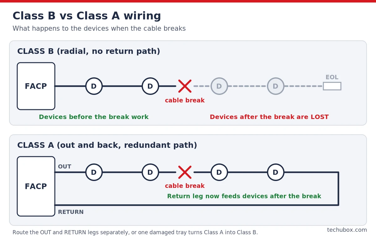
The T-tap rule
On a Class B conventional zone or NAC, supervision only works if every device is “in and out” and the EOL is last. If you tee a branch off the middle, the branch has no EOL of its own, so a break on it changes nothing the panel can measure. The rule I teach is simple: on conventional circuits, every terminal has a cable in and a cable out, or a cable in and the EOL. Class B addressable loops are different, because supervision is by communication: a missing device is reported however you wired it, so T-taps are allowed there if the manufacturer permits. On Class A and Class X circuits, T-taps are not allowed, because they would defeat the redundant path.
One more Class A detail: the outgoing and return conductors should not run in the same cable or the same tray if you can avoid it. NFPA 72 has separation requirements for Class A and Class X pathways, with some exceptions for short runs. A loop whose two legs share one cable is Class A on paper and Class B the day someone cuts that cable.
Survivability: will the wire last long enough?
Class tells you what the circuit does when it is damaged. Survivability tells you how long the circuit lasts in a fire. That matters most where people are not all evacuated at once, such as high-rise buildings with phased evacuation or voice systems that must keep speaking to floors that are not yet affected. NFPA 72 uses pathway survivability levels:
- Level 0: no survivability requirement.
- Level 1: the building is fully sprinklered and the cable runs in metal raceway.
- Level 2: two-hour protection, typically a two-hour rated cable or a two-hour rated enclosure or protected area.
- Level 3: Level 2 protection plus a fully sprinklered building.
The building code and the evacuation strategy decide which level applies, not the installer. In British practice, BS 5839-1 talks about “standard” and “enhanced” fire-resisting cables, and the choice depends on the building and evacuation strategy. In the GCC, specifications often simply ask for fire-resistant, low-smoke cable for the whole system, which removes the debate on site. My high-rise article goes deeper: Fire Alarm Design for High-Rise Buildings.
- Class A loops with both legs in one cable for the last 30 m “because the tray was full”.
- T-taps on a conventional zone hidden inside a ceiling junction box.
- Fire-rated cable fixed with plastic ties to a cable tray. In a fire, the ties melt and the cable falls. Use metal fixings or supports suitable for the cable’s fire rating.
- Standard PVC cable spliced into a fire-rated circuit at a junction box.
Class describes behaviour under fault; survivability describes endurance under fire. You need both. Ask for them in the design, and protect them during installation with routing, separation and fixings.
Module 8 quiz (tap to open)
- What is the difference between Class A and Class X?Class A survives a single open; Class X also survives a single short and an earth fault, usually by using isolators on a redundant path.
- Why are T-taps permitted on Class B addressable loops but not on conventional zones?Loops are supervised by communication, so a lost device is still reported. Conventional zones rely on current through one EOL.
- Which survivability level combines two-hour protection with a fully sprinklered building?Level 3.
MODULE 9Detector Types, Selection and Spacing Basics
- Match each detector type to the fire and the environment it suits.
- Apply basic spacing rules for spot smoke and heat detectors.
- Avoid the placement errors that cause false alarms.
Picking a detector is a two-part question: what kind of fire is likely in this room, and what will the room do to the detector the rest of the time? A smoke detector in a dusty plant room or a steamy kitchen will false alarm until someone disables it, and a disabled detector protects nobody.
| Detector | Senses | Good for | Avoid or think twice |
|---|---|---|---|
| Optical (photoelectric) smoke | Light scattered by smoke particles | Offices, corridors, hotel rooms, escape routes | Kitchens, steam, heavy dust |
| Ionisation smoke | Change in ionised air current | Fast flaming fires (legacy installs) | Largely phased out; contains a radioactive source with disposal rules |
| Multi-sensor (smoke + heat, sometimes CO) | Combined signals analysed together | Mixed areas, hotel rooms, where false alarms are a concern | Check mode settings match the room |
| Heat, fixed temperature | Temperature above a set point | Kitchens, boiler rooms, dusty areas | Slow to respond; not for sleeping risk escape routes |
| Heat, rate of rise | Rapid temperature increase | Stores, car parks, plant areas | Spaces with sudden normal heat (oven doors, hot air blasts) |
| Optical beam | Smoke obscuring an infrared beam | Warehouses, atriums, halls with high ceilings | Buildings that flex or vibrate; must be fixed to solid structure |
| Aspirating (ASD) | Air drawn through pipes to a sensitive chamber | Data centres, clean rooms, heritage spaces, cold stores | Needs careful pipe design and commissioning |
| Flame (UV, IR, multi-IR) | Radiation from flames | Fuel areas, hangars, oil and gas, generator rooms | Needs line of sight; watch for sunlight and welding |
| Duct smoke | Smoke in air ducts | Shutting down AHUs before they spread smoke | Not a replacement for room detection |
For more depth on two of the most common choices, read Smoke vs Heat Detector and my guide to flame detectors.
Spacing basics: the two schools
NFPA approach. Spot-type smoke detectors on smooth, flat ceilings commonly use a nominal spacing of 9.1 m (30 ft) between detectors, half that to a wall, and a check that every point on the ceiling is within 0.7 × the spacing (about 6.4 m) of a detector. Heat detectors use their listed spacing, which is reduced as ceilings get higher. The 2025 edition introduced a 40 ft (about 12.2 m) ceiling height limit for the prescriptive spacing of spot-type smoke detectors; above that, you need a performance-based design or a different detection method.
BS 5839-1 approach. On flat ceilings, no point should be more than 7.5 m from a point smoke detector or 5.3 m from a point heat detector, measured horizontally, with adjustments for corridors, apexes and high ceilings.
An office is 18 m × 12 m with a flat 3 m ceiling and no deep beams.
- NFPA-style layout: 18 ÷ 9.1 rounds up to 2 columns; 12 ÷ 9.1 rounds up to 2 rows. Place 4 detectors at 9 m × 6 m centres, which puts them 4.5 m and 3 m from the walls.
- Check the worst point, the corner: √(4.5² + 3²) = √29.25 ≈ 5.4 m, which is inside 6.4 m.
- BS-style check: the same 5.4 m is inside the 7.5 m radius too, so 4 detectors work for both approaches.
- Now add reality: a supply diffuser sits 0.5 m from one detector position. Move the detector away from it, keeping at least about 1 m from supply and return grilles, and recheck the corner distances.
To see this on a real plan, drop the room into the Fire Alarm Design Tool and watch the coverage circles. It is the fastest way to build intuition for spacing.
Placement rules that prevent false alarms
- Keep spot detectors away from air supply diffusers and returns; moving air dilutes or pushes smoke away.
- Beams, ducts and deep joists change how smoke travels; deep obstructions may need a detector in every bay.
- Keep detectors out of the dead air in corners where the wall meets the ceiling, and follow the specific distances your standard sets for that.
- Do not put smoke detectors next to kitchen doors, shower rooms or loading dock shutters. Use heat or multi-sensor there.
- Leave the dust covers on during construction, then remove them before handover. A detector with its cover on is just decoration.
- Detectors installed above a false ceiling grid tile line without checking the void that also needs protection.
- Smoke detectors in a dusty generator room, then the whole zone disabled after the third false alarm.
- Beam detectors on a steel structure that moves with heat in the afternoon, causing beam faults daily.
Choose the detector for the fire and the room, then space it to the standard your project follows. Most false alarms are decided at the drawing stage, not by the detector.
Module 9 quiz (tap to open)
- Which detector type suits a commercial kitchen?A heat detector (fixed temperature is the usual choice), not a smoke detector.
- Under BS 5839-1, what is the maximum horizontal distance from any ceiling point to a point heat detector?5.3 m (7.5 m for point smoke detectors).
- What changed for spot smoke detectors in the 2025 edition of NFPA 72?A 40 ft ceiling height limit for prescriptive spacing of spot-type smoke detectors.
MODULE 10Manual Call Points
- Place call points at exits and within the right travel distance.
- Set the correct mounting height for NFPA and BS projects.
- Choose the right call point type for the environment.
Detectors may take a minute to sense a fire. A person who sees flames reacts in seconds. Manual call points let them raise the alarm on their way out, so they belong on the route people take when they leave: at exits, at stair doors and along long escape routes. In KSA, SBC 801 also expects at least one manual fire alarm box even on systems that are otherwise automatic or sprinkler driven.
| Rule of thumb | NFPA-style projects | BS 5839-1 projects |
|---|---|---|
| Where | Within about 1.5 m (5 ft) of each exit doorway on each floor | At every storey exit and every exit to open air |
| Height | Operable part between about 1.07 m and 1.22 m (42–48 in) | About 1.4 m above floor, lower where wheelchair users need it |
| Travel distance | Additional boxes so no one walks more than about 61 m (200 ft) | No one should travel more than 45 m to reach one (25 m in some higher-risk cases) |
| Colour and type | Red, single or dual action as specified | Red, Type A (operating element), often with protective cover |
In car parks, kitchens and outdoor areas, use weatherproof versions with the right IP rating. Hinged protective covers reduce accidental and malicious activations in schools and malls; some include a local warning sounder when lifted. Use the green emergency door release units for access control, never a red call point: the two must look different, and they do different jobs.
A hotel floor has a 70 m corridor with a stair at each end. BS 5839-1 project: put call points at both stair doors. The farthest room door is mid-corridor, 35 m from each stair, which is inside the 45 m travel distance, so two call points work. Then check the lift lobby exit and any exit to an external terrace; each one needs its own.
- Call points on the room side of a door instead of the escape side.
- Mounted behind an opening door leaf, so they are hidden when the door is open.
- Conventional call points wired without the correct alarm resistor, so the panel reads a fault instead of a fire, or the other way round.
Call points go where people leave, at a height they can reach, close enough that nobody has to walk far to raise the alarm. Check the height and the travel distance against the standard your project uses.
Module 10 quiz (tap to open)
- On a BS 5839-1 project, what is the normal maximum travel distance to a call point?45 m (25 m in some higher-risk situations).
- Why should a call point not be mounted behind an opening door?It is hidden when the door is open, which is exactly when people are using the exit.
- What colour is a door emergency release unit for access control?Green, so it is not confused with the red fire alarm call point.
MODULE 11Sounders and Strobes: Audibility and Visibility
- Estimate sound level at a distance using the inverse square rule.
- Know the common target levels for public spaces and sleeping areas.
- Understand how strobe coverage is expressed in NFPA and EN 54-23 terms.
A warning that people cannot hear or see is not a warning. Sounder design is mostly about the room, not the sounder: how noisy it is normally, how many doors and walls sit in the way, and whether people inside may be asleep, wearing ear protection or unable to hear.
Audibility targets
Common learning values are worth memorising. On NFPA-style projects, public mode signals are typically designed to be at least 15 dB above the average ambient sound level in the space. In sleeping areas, the signal at the pillow must also be loud enough to wake people, and NFPA requires a low-frequency (520 Hz) tone for many sleeping areas, because it wakes people more reliably. On BS 5839-1 projects, the familiar figures are a minimum of 65 dB(A) in general areas, or 5 dB above any background noise likely to last more than about 30 seconds, and 75 dB(A) at the bedhead where people need waking. Check the exact conditions in the current edition you work to.
A sounder is rated 95 dB(A) at 1 m. In open space, sound falls about 6 dB each time the distance doubles, which is the inverse square rule: L = L₁ − 20 × log₁₀(d).
- At 4 m: 95 − 20 × log₁₀(4) = 95 − 12 = 83 dB(A).
- At 8 m: 95 − 18 = 77 dB(A).
- At 16 m: 95 − 24 = 71 dB(A).
- The office ambient is 55 dB(A), so an NFPA-style target is about 70 dB(A). One sounder covers roughly a 16 m radius in open space, before walls.
- Now a closed office door. A typical door can cut 20 dB or more, so a corridor sounder that gives 77 dB(A) outside gives perhaps 55–57 dB(A) inside. That is not enough. Put a sounder (or sounder base) inside the office.
The lesson: in cellular buildings like hotels and hospitals, plan a sounder per room, not per corridor.
Do not overshoot either. Very high levels near a sounder are uncomfortable and can be harmful, and they make voice messages harder to understand. Spreading more, quieter sounders evenly beats a few very loud ones. In large or complex buildings, voice evacuation is often the better answer; the PA System Designer helps you lay out speakers and estimate coverage when the project combines public address with voice alarm.
Visibility: strobes and VADs
Strobes help people who are deaf or hard of hearing, and anyone in very noisy places. In NFPA terms, strobe output is given in candela (cd), and tables in NFPA 72 link room size and mounting position to the required rating. As a feel for the numbers, a single wall-mounted strobe in a room of about 6 × 6 m (20 × 20 ft) typically needs 15 cd, and bigger rooms need much higher ratings or more units. Ceiling and wall strobes use different tables, so check the mounting before you pick the rating.
In European practice, EN 54-23 describes visual alarm devices by coverage category instead. A code such as W-2.4-7.5 means a wall-mounted device, at a mounting height of 2.4 m, that covers a cube 7.5 m wide. A ceiling device might be written C-3-10: ceiling mounted, up to 3 m high, covering a cylinder 10 m in diameter. You lay out VADs by those coverage figures, the same way you lay out detectors by radius.
- One sounder per corridor in a hotel, with nothing inside the rooms.
- Sound level measurements taken with the HVAC switched off, so the real ambient is higher than measured.
- Wall strobes mounted above a high-level cable tray where nobody can see them.
- Mixing strobe brands that do not synchronise together.
Design for the listener: measure the ambient, allow for doors and walls, and target the levels your standard sets. Lay out strobes by their rated coverage, keep them synchronised and keep them visible.
Module 11 quiz (tap to open)
- A sounder gives 89 dB(A) at 2 m. Roughly what will it give at 8 m in open space?Two doublings of distance: 89 − 6 − 6 ≈ 77 dB(A).
- What does the EN 54-23 code W-2.4-7.5 describe?A wall-mounted VAD at 2.4 m height covering a 7.5 m cube.
- Why is a 520 Hz tone used in many sleeping areas on NFPA projects?A low-frequency tone is more effective at waking sleeping people.
MODULE 12Power Supplies and Battery Standby Calculation
- Collect standby and alarm currents for every powered item.
- Calculate battery capacity for the required standby and alarm times.
- Add a sensible margin and pick a real battery size.
Battery sizing is where I see the most guesswork, and it is one of the easiest calculations in the whole course. You need three things: the current the system draws in standby, the current it draws in alarm, and how long it must run in each state on batteries alone.
Durations come from the standard and the specification. Typical learning values: NFPA 72 commonly asks for 24 hours of standby followed by 5 minutes of alarm for a general alarm system, and 15 minutes of alarm for voice evacuation systems. BS 5839-1 projects commonly use 24 hours of standby followed by 30 minutes of alarm, with longer standby in some cases (for example, where the building is unoccupied for longer periods or there is no standby generator). Your specification and the local authority may set longer times, so use theirs.
| Item | Standby current (A) | Alarm current (A) |
|---|---|---|
| Panel (main board, display) | 0.150 | 0.300 |
| Loop 1 devices | 0.070 | 0.120 |
| Loop 2 devices | 0.065 | 0.120 |
| Repeater panel and network card | 0.045 | 0.060 |
| Sounders and strobes (NACs) | 0.000 | 2.100 |
| Total | 0.330 | 2.700 |
- Standby capacity: 0.330 A × 24 h = 7.92 Ah.
- Alarm capacity, NFPA-style 5 minutes: 2.700 A × (5 ÷ 60) h = 0.225 Ah.
- Subtotal: 7.92 + 0.225 = 8.15 Ah.
- Design margin: I add 25% for ageing, temperature and future devices: 8.15 × 1.25 = 10.2 Ah.
- Choose the next standard size: 2 × 12 V 12 Ah in series for a 24 V panel, if the panel’s charger and cabinet are rated for it.
- Same panel on a BS-style 30-minute alarm: 2.700 × 0.5 = 1.35 Ah; subtotal 9.27 Ah; with 25% margin, 11.6 Ah. A 12 Ah pair is now right at the edge, so I would choose the next size up (often 17 or 18 Ah, if the cabinet and charger allow).
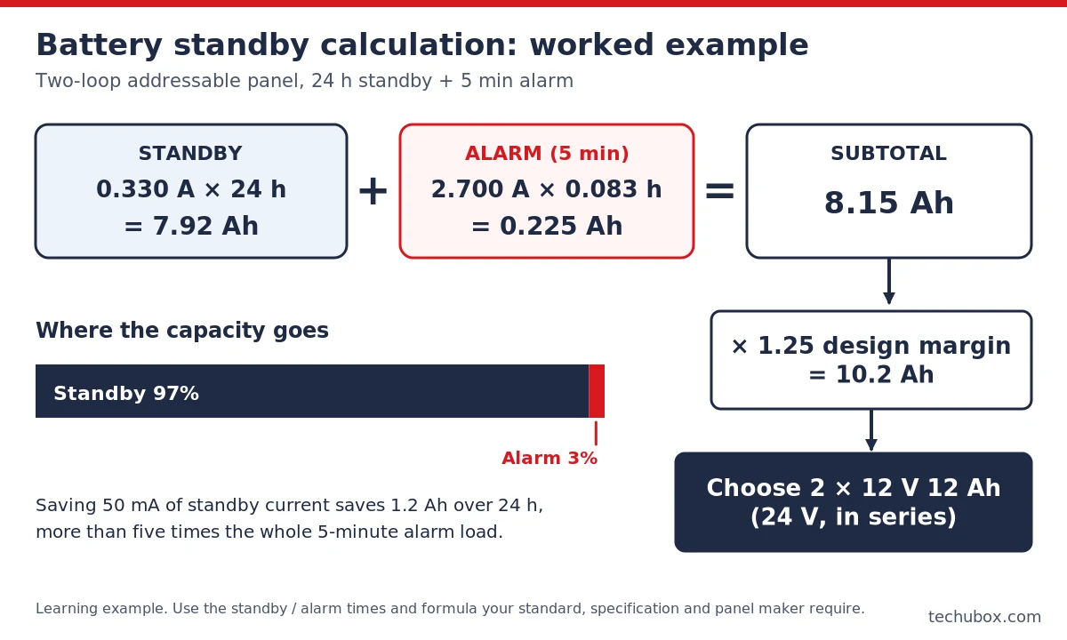
Notice where the capacity goes: 97% of it is standby. Shaving 50 mA off the standby current saves 1.2 Ah over 24 hours, while the whole 5-minute alarm costs only 0.225 Ah. That is why low-power loop devices matter more than you might think. Some manufacturers and standards give their own formula with specific factors for battery ageing and alarm load; when they do, use that formula and show it in the submittal. The Techubox Battery Backup Calculator runs the same steps for you and is handy for checking a supplier’s figure.
Batteries in a hot climate
Sealed lead-acid batteries age much faster when hot. In a Gulf plant room without cooling, a battery that should last several years may lose capacity far sooner. Keep panels in conditioned spaces where possible, date-label every battery, and test them as your maintenance standard requires. Check the charger output and the panel’s battery-fault detection at every service.
- Leaving out repeater panels, auxiliary supplies, beam detectors or interface units.
- Using the sounder’s “typical” current instead of its maximum at low voltage.
- Fitting a bigger battery than the panel’s charger or cabinet is designed for.
- Batteries with no installation date, so nobody knows when to replace them.
Capacity = (standby current × standby hours) + (alarm current × alarm hours), plus a margin. Collect every load honestly and the battery size almost picks itself.
Module 12 quiz (tap to open)
- A system draws 0.5 A standby and 3 A in alarm. Find the capacity for 24 h standby and 30 min alarm, before margin.0.5 × 24 = 12 Ah; 3 × 0.5 = 1.5 Ah; total 13.5 Ah.
- Which state usually dominates the battery size?Standby, because it lasts 24 hours or more.
- Why add a margin?To cover battery ageing, temperature effects, tolerance and future additions.
MODULE 13The Cause and Effect Matrix
- Read a cause and effect matrix and explain each mark.
- Write a simple matrix for a small building.
- Use the matrix as the test script during commissioning.
The cause and effect matrix, or C&E, is the single most useful document on a fire alarm project. It is a grid. Rows are the causes: every input or group of inputs. Columns are the effects: every output. A mark where a row and a column meet says “when this happens, do that”. Everyone involved, from the consultant and the MEP contractor to the lift company and Civil Defense, can read it without knowing the panel software.
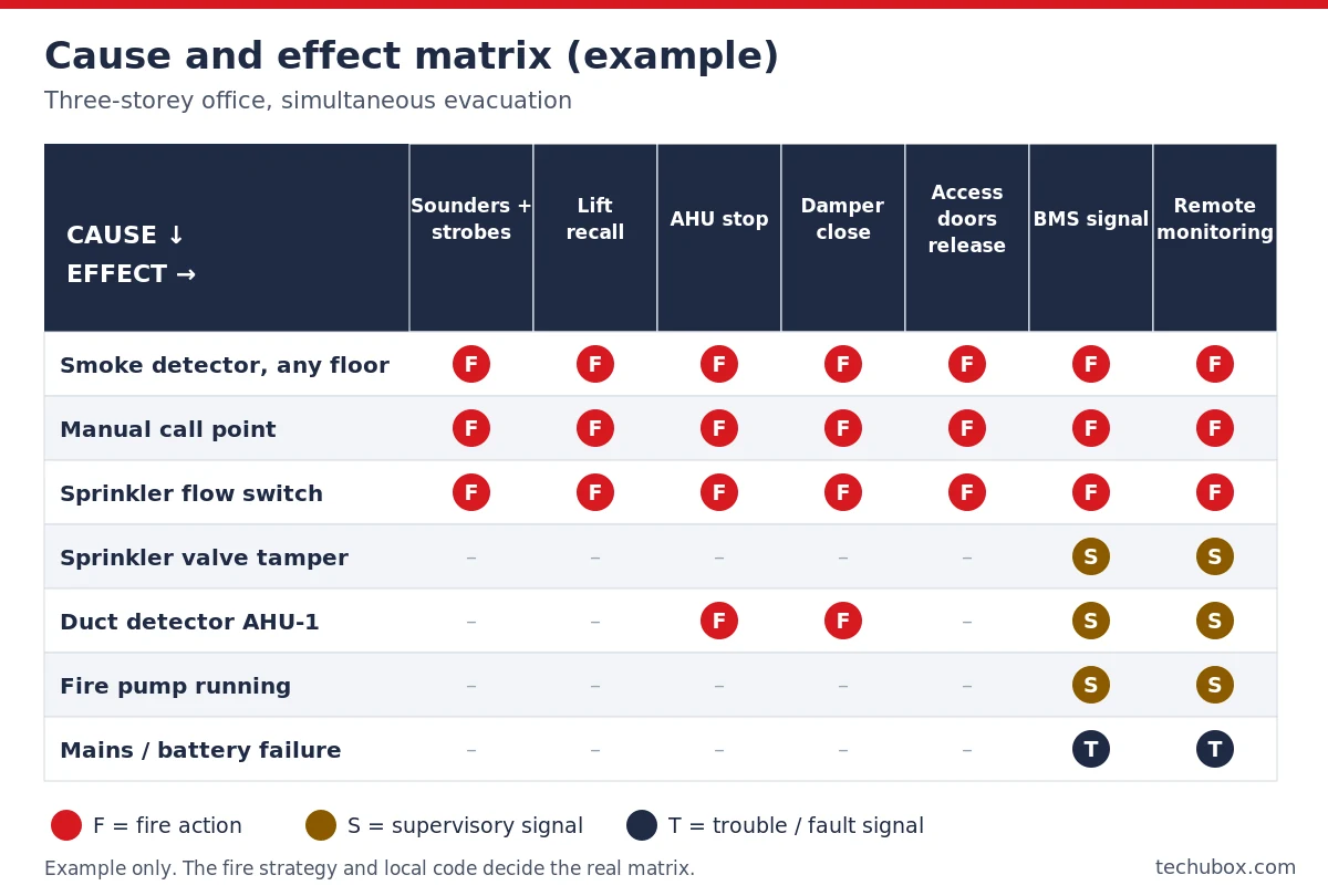
Here is the same matrix in a form you can copy and adapt:
| Cause ↓ / Effect → | All sounders and strobes | Lift recall | AHU stop (floor) | Smoke damper close | Access doors release | Signal to BMS | Remote monitoring |
|---|---|---|---|---|---|---|---|
| Smoke detector, any floor | F | F | F | F | F | F | F |
| Manual call point, any floor | F | F | F | F | F | F | F |
| Sprinkler flow switch | F | F | F | F | F | F | F |
| Sprinkler valve tamper | – | – | – | – | – | S | S |
| Duct smoke detector, AHU-1 | – | – | F (AHU-1) | F | – | S | S |
| Fire pump running | – | – | – | – | – | S | S |
| Mains or battery failure | – | – | – | – | – | T | T |
Some notes on this example. In many buildings, a duct detector shuts down its own AHU and signals supervisory rather than starting a full evacuation, but that depends on the local code and the fire strategy. Phased evacuation buildings replace “all sounders” with “alert on adjacent floors, evacuate on fire floor”. Lift recall usually has a primary and an alternate floor, chosen by which floor the alarm is on. Every one of those decisions belongs in the matrix before programming starts.
Pick row 1, “Smoke detector, any floor”. At commissioning, operate a detector on level 2 with test smoke and tick each effect column as you witness it: sounders on all floors, lifts home to the ground floor with doors open, AHU on level 2 stops, dampers on level 2 close (with feedback), access doors release, BMS shows the alarm, the monitoring centre receives it. Then reset and repeat for one device on every other floor. When every mark has a tick and a signature, the C&E is proven.
I also explain C&E in a wider integration context in Fire Alarm Integration with BMS, Access Control and CCTV, and the Exit Plan Designer is useful for matching the matrix to the escape routes and call point positions on a floor plan.
- Programming the panel first and writing the matrix afterwards to match whatever it does.
- A matrix with “all doors” instead of a door schedule, so nobody knows which doors release.
- No column for reset behaviour, so dampers or lifts stay in fire mode after the alarm is cleared.
The C&E is the contract between the fire strategy and the panel software. Agree it with every trade before programming, and use it line by line as the commissioning test script.
Module 13 quiz (tap to open)
- In a C&E matrix, what do rows and columns represent?Rows are causes (inputs), columns are effects (outputs).
- What signal family would a sprinkler valve tamper normally produce?Supervisory.
- Name one decision that must be in the matrix before programming lift recall.The primary and alternate recall floors, and which alarms send the lift to each.
MODULE 14Interfaces: Sprinklers, BMS, Lifts, AHUs and Access Control
- Connect sprinkler flow and tamper switches correctly.
- Decide what the BMS should and should not do in a fire.
- Agree interface responsibilities with other trades in writing.
Most commissioning delays I have seen were not fire alarm problems. They were interface problems: a lift that would not recall, a damper with no feedback, an access door that stayed locked because the lock power came from a different supply. The fire alarm contractor usually provides the contact; the other trade decides what happens on the other side of it. Make that boundary crystal clear.
Sprinkler flow and tamper switches
A flow switch (paddle type in the pipe, or a pressure switch on alarm check valves) closes when water flows. It is wired to a monitor module or a dedicated zone and programmed as a fire alarm. Most flow switches have an adjustable delay so that pressure surges do not cause false alarms; set it as the sprinkler designer and the standards require, and prove it at the inspector’s test valve. A tamper switch on a control valve operates when the valve starts to close. It is programmed as supervisory, never as fire. Use a separate input for each valve when you can, so the panel tells you exactly which valve is shut.
BMS
The building management system should know about fire alarms, but it should not be the thing that makes life-safety actions happen. Hard-wired relays from the fire alarm stop fans and close dampers; the BMS gets a copy of the status for display, logging and energy shutdown of non-critical plant. High-level interfaces (BACnet, Modbus or vendor gateways) are common now. They are great for information, but treat them as read-only from the fire alarm’s point of view unless the standard, the AHJ and the panel listing allow otherwise. With panels now on networks, the 2025 edition of NFPA 72 adds a chapter on cybersecurity (Chapter 11), which is a good reason to keep fire alarm networks segregated and gateways locked down.
Lifts
Lift recall needs inputs from the fire alarm to the lift controller, typically separate signals for primary recall, alternate recall and, where required, a warning for a machine room or hoistway detector. The lift contractor decides the controller logic; the fire alarm contractor proves the contacts change. Agree the voltages, contact types and the floor plan for recall in a signed interface sheet.
AHUs, fans and smoke control
AHU shutdown is normally a fire alarm relay in the starter control circuit, plus duct smoke detection where the code calls for it. Smoke extraction and stair pressurisation are the opposite: they must start on alarm, so their commands need supervision and feedback, and often a firefighter control panel. Do not let a generic “fire stop all fans” relay also stop the stair pressurisation fans.
Access control and doors
Escape doors controlled by access control must release on fire alarm. I always design the release as hard-wired and fail-safe: a fire alarm relay contact in series with the lock power, plus a green break-glass at the door. A software command through the access control server is a nice extra, not the safety function. The full wiring and testing story is in access control and fire alarm integration.
| Interface | FA contractor provides | Other trade provides | Proof at commissioning |
|---|---|---|---|
| Sprinkler flow | Monitor module, programming | Flow switch, delay setting | Flow at inspector’s test valve gives alarm within the set delay |
| Valve tamper | Monitor module, supervisory programming | Switch on valve | Partly closing the valve gives a supervisory signal |
| Lift recall | Relay contacts per signal | Lift controller logic | Car returns to correct floor, doors open, car parks |
| AHU / damper | Relay, feedback input | Starter wiring, actuators | Fan stops, damper closes, feedback reported |
| Access control | Fail-safe relay in lock power | Lock power, door hardware | Every listed door releases on alarm and on mains failure |
| BMS | Gateway or volt-free contacts | BMS points and graphics | BMS shows correct alarm and fault points |
- Tamper switches programmed as fire, so closing a valve for maintenance evacuates the building.
- Lift recall wired but never tested with the lift contractor present.
- Door release done only through the access control software.
- BMS given write access to the fire panel “for convenience”.
The fire alarm provides a clean, tested contact and the other trade does the rest. Write the boundary down, test it together, and keep life-safety actions hard-wired.
Module 14 quiz (tap to open)
- Should a tamper switch be programmed as fire or supervisory?Supervisory.
- Why should door release on escape routes be hard-wired?So doors release even if the access control server, network or software fails.
- Which NFPA 72 chapter in the 2025 edition covers cybersecurity?Chapter 11.
MODULE 15Step-by-Step Termination Guide
- Prepare cables and test them before any device is connected.
- Terminate detector bases, call points, modules, sounders and panel loops in a safe order.
- Handle the screen (drain) and earth so the panel stays free of earth faults.
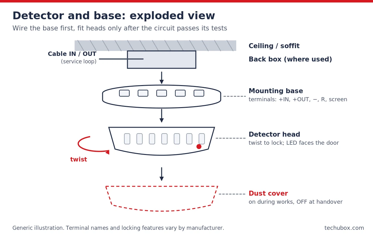
This is the module I wish every new technician read before touching a screwdriver. Good termination is quiet: nobody notices it. Bad termination shows up as intermittent faults, earth faults and false alarms for years. Terminal names below are generic. Every manufacturer labels its bases and modules differently, so the datasheet and installation sheet for the exact product always win over this guide.
- On a live building, tell the building management, the monitoring centre and, if required, Civil Defense before you work. Put affected zones or loops into a controlled disablement on the panel, and disable outputs such as lift recall, door release and plant shutdown so your work does not trigger them. Log what you disabled.
- Before working inside the panel, isolate the mains supply at its dedicated fused spur or breaker, lock it off and label it, then disconnect the batteries. Remember the batteries can deliver a large current even when mains is off.
- Never carry out an insulation resistance (megger) test with devices or the panel connected. The test voltage can damage electronics.
- Wear eye protection when stripping fire-resistant cable, and use proper access equipment for ceiling work.
Before any termination: prepare and test the cable
- Confirm the cable type matches the specification (fire-resistant grade, core size, screen) and that runs follow the approved route, with metal fixings where fire resistance matters.
- Identify every core at both ends and fit ferrules or markers: loop number, out/return, device address or zone number.
- Strip the outer sheath carefully without nicking the core insulation. Keep the screen (drain) wire and cut back any foil neatly.
- With both ends free and nothing connected, test continuity of each core and the screen.
- Carry out an insulation resistance test between cores, and between each core and the screen and earth, at the test voltage your specification sets (500 V DC is common for this type of cable). Record the readings. Very high readings are what you want; any low reading must be traced before you go further.
- Leave a neat service loop in each back box so a base can be replaced later without stretching the cable.
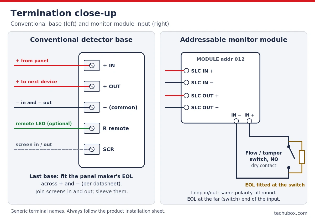
1. Conventional detector base
- Fix the base to the back box or ceiling and level it so the head will sit flat.
- Connect the incoming positive core to the base’s positive (often marked L1 or +) IN terminal and the outgoing positive core to the OUT terminal, if the base has separate terminals. Separate in and out terminals let the circuit break when a head is removed, which is how the panel sees a missing detector.
- Connect incoming and outgoing negative cores to the negative (often L2 or −) terminal, or to the in and out negative terminals if provided.
- If a remote indicator LED is used (for detectors in locked rooms or voids), connect it to the remote terminal and the polarity the datasheet shows.
- Join the incoming and outgoing screen wires on the screen or earth terminal, or in a connector. Sleeve them so they cannot touch live terminals or the base metalwork.
- On the last base of the zone, fit the panel maker’s EOL resistor (or EOL device) across positive and negative, as the datasheet shows. Write “EOL” on the base or ceiling grid for the next technician.
- Tug-test every conductor, then fit the head only after the zone has passed its tests.
2. Addressable detector base
- Set or record the address. Some heads use rotary switches or DIP switches, some are set with a handheld programmer, and some take an address automatically. Write the address on the base and the as-built drawing.
- Connect loop IN positive and negative, and loop OUT positive and negative, to the terminals the datasheet shows. Keep polarity consistent around the whole loop.
- If the base has a built-in isolator, note which side is “in” and which is “out”; on some isolator bases this matters.
- Join the screen through as for the conventional base. No EOL resistor is needed on the loop itself.
- Fit heads after the loop has passed continuity, insulation and loop resistance checks.
3. Manual call point
- Mount the back box at the height and position from Module 10, on the escape side of the door.
- Conventional call point: connect the zone in and out cores. Make sure the switch circuit includes the alarm resistor the panel maker requires (many call points have it fitted; some need a link or resistor added). The resistor makes the call point look like a detector in alarm, not a dead short.
- Addressable call point: set the address, then terminate loop in and loop out like a detector base.
- Carry the screen through. Fit the front, and check the test key operates and resets it.
4. Monitor (input) module
- Mount the module near the device it monitors (for example, next to the sprinkler valve), inside a suitable enclosure if it is a loose module.
- Terminate loop in and loop out, with the screen carried through.
- Run a pair from the module’s input terminals to the switch. Use the switch’s normally open contact for a flow switch or for a “pump running” signal, unless the module’s instructions say otherwise.
- Fit the module’s EOL resistor at the switch end, not at the module, so the panel supervises the whole cable to the switch. Some modules also need a series alarm resistor; follow the datasheet.
- Program the address with the correct type: fire for flow, supervisory for tamper, and a clear location text.
5. Control (output) module
- Terminate loop in and loop out, with screen.
- For a dry relay output, wire the other system’s control circuit through C and NC for a fail-safe stop or release, or C and NO where the other system needs a closing contact to act. Check the contact rating against the actual load.
- For a supervised output, connect the external 24 V DC supply (from a monitored fire alarm power supply) to the module’s supply terminals, wire the output to the load, and fit the EOL at the far end as the datasheet shows.
- Label the interface cable at both ends with its function, for example “AHU-2 stop, FA relay C/NC”.
- Never bring 230 V into a module that is only rated for low-voltage signalling. Use an interposing relay or the starter’s own control circuit.
6. Sounder, strobe and NAC appliances
- Check the appliance settings before closing it: tone, volume, candela setting and sync mode must match the design.
- Connect incoming + and − to the IN terminals, outgoing + and − to the OUT terminals. Polarity is critical on reverse-polarity NACs.
- Do not put two cables under one screw to bypass the appliance terminals; the circuit must break if the appliance is removed, where the product supports this.
- Fit the NAC EOL resistor at the last appliance. On addressable sounder circuits, follow the loop rules instead.
- Record the appliance setting and its location on the as-built drawing.
7. Panel loop and zone terminals
- With mains isolated and batteries disconnected, dress the cables into the panel through the correct glands, keeping fire alarm cables apart from the mains feed.
- Before landing the loop, measure the loop resistance (out leg to return leg, positive and negative separately) and compare with the panel maker’s maximum. Check the device count and, if the manual gives one, the loop capacitance limit.
- Land loop OUT + and − and loop RETURN (IN) + and − on the loop card terminals. Check that polarity is the same at both ends.
- For conventional zones, land each zone pair on its terminals and remove any test EOLs that were fitted at the factory, because the real EOL is now at the last device.
- Land NAC circuits and any relay outputs, keeping each labelled.
- Reconnect batteries with the correct polarity, then restore mains. Watch the panel start up and read every fault message before you clear anything.
8. Earth and screen
- Carry the screen continuously through every device on the circuit, joined in each back box.
- Connect the screen to earth at one point only, normally at the panel’s designated earth or screen terminal. Earthing at both ends can create loops that inject noise.
- Make sure the panel’s protective earth from the mains supply is connected and tight.
- After power-up, check the panel’s earth-fault indication. If it reports an earth fault, disconnect circuits one at a time until it clears; the last one you removed is the faulty circuit.
When a fault does appear, my troubleshooting guides go step by step: Open-Circuit Faults in Fire Alarm Systems and the Addressable Fire Alarm Fault and Troubleshooting Guide.
- Megger testing with the panel or devices still connected.
- Screen wire left loose in the back box, touching the base metalwork and causing an earth fault.
- EOL resistors fitted in the panel “for testing” and never moved to the field.
- Copper strands sticking out of a terminal, bridging to the next one in hot weather.
Test the cable before you connect anything, terminate in and out on separate terminals, keep polarity consistent, put the EOL at the far end, and earth the screen at one point only. Do that and most faults never happen.
Module 15 quiz (tap to open)
- Where does the EOL resistor for a monitor module input go?At the switch end of the input cable, so the whole cable is supervised.
- Why is the screen earthed at one point only?Earthing at more than one point can create earth loops and noise on the circuit.
- What must you do before an insulation resistance test?Disconnect all devices and the panel, so the test voltage cannot damage electronics.
MODULE 16Acceptance Testing and Commissioning
- Explain the difference between commissioning and acceptance testing.
- Run a 100% device and function test in a logical order.
- Know what the authority will expect to see on handover day.
People often use these words loosely. Commissioning is the whole process of proving the system works as designed, from the first power-up through programming, functional tests and integrated testing with other systems. Acceptance testing is the formal witnessed test at the end, where the owner, consultant and authority confirm that the installed system does what the approved design says. In KSA, the Civil Defense inspection sits at the end of that process.
A sensible commissioning order
- Installation inspection. Walk every area against the approved drawings: device types, positions, spacing, heights, labels, cable routes, fixings and fire stopping where cables pass through walls.
- Cable tests. Continuity, insulation resistance and loop resistance on every circuit, recorded on test sheets.
- Power-up and configuration. Correct panel software version, loop learning, address list checked against the drawings, location texts, zones, sensitivities and day/night modes.
- Device tests. Every detector with the correct test method (test smoke for smoke detectors, a heat source for restorable heat detectors, a test filter or the maker’s method for beams), every call point with its test key, every module input operated at the field device.
- Fault tests. Open circuit, short circuit and earth fault on sample circuits, plus mains failure and battery disconnect, each checked for the correct indication.
- Notification tests. Sound level readings with a calibrated meter in representative rooms, with normal background noise; strobes checked for operation and sync; voice messages checked for clarity.
- Cause and effect tests. Every line of the matrix witnessed, including lifts, AHUs, dampers, doors, BMS and remote monitoring.
- Battery test. Measured standby and alarm currents compared with the calculation, and a load test on the batteries as the standard requires.
- Witness test and handover. Repeat the tests the client and authority want to see, then hand over the documents.
A hotel has 900 addressable devices. With two technicians and a radio, a realistic pace for smoke testing in occupied-style rooms is around 25–35 devices per hour per pair, including access and resets. At 30 per hour, 900 devices is about 30 hours, so four working days for device tests alone, before C&E, sound levels and interfaces. Planning for one day is how commissioning gets rushed and devices get skipped.
- “Testing” detectors with a magnet or panel walk-test only, without smoke reaching the chamber.
- Sound level readings taken in an empty, silent building at night.
- Interfaces tested without the other trade present, then “tested” again at the authority visit, live, for the first time.
- Test results kept in a WhatsApp group instead of signed test sheets.
Test every device, every fault condition and every line of the C&E, record it on signed sheets, and only then invite the authority. A witness test should be a repeat, not a discovery.
Module 16 quiz (tap to open)
- What is the difference between commissioning and acceptance testing?Commissioning is the full process of proving the system; acceptance testing is the formal witnessed test at the end.
- Why is a magnet test not enough for a smoke detector?It does not prove smoke can enter the chamber and be sensed.
- Name three fault conditions you should simulate.Open circuit, short circuit, earth fault (also mains failure and battery disconnect).
MODULE 17Inspection, Maintenance and Documentation
- Describe the routine of visual inspection, testing and maintenance.
- Handle a system impairment safely.
- List the documents a complete handover package contains.
A fire alarm that passed its acceptance test five years ago and has not been looked after since is a gamble. Buildings change: walls move, ceilings get lowered, a tenant turns an office into a kitchen, and detectors collect dust. Inspection, testing and maintenance (ITM) keep the system matched to the building it protects.
The routine in plain words
- Visual inspections look for damage, missing devices, painted or covered detectors, blocked call points, storage stacked up to the ceiling and new partitions that block coverage.
- Functional tests operate devices and check the right signal and response. Under NFPA 72, many devices are tested every year, and smoke detector sensitivity is checked at set intervals after installation. Under BS 5839-1, the user tests a different call point every week to prove the system sounds, and a competent person services the system at intervals not exceeding six months, so that every device is tested over the year.
- Maintenance is mostly cleaning, replacing batteries and devices at the end of their life, and keeping software and documentation current. Analogue addressable panels help a lot here: their drift and contamination reports tell you which detectors need cleaning before they false alarm.
Exact frequencies come from the tables in the current edition of your standard and from the local authority, so put them in your maintenance contract rather than relying on memory. SBC 801 also sets its own maintenance and record-keeping expectations in KSA.
Impairments and false alarms
Whenever part of the system is disabled, whether for hot works, maintenance or a fault, treat it as an impairment: tell the building management and the monitoring centre, record what is disabled and why, put fire watch or other measures in place if required, and re-enable and test as soon as the work ends. Most disabled zones I find were “temporary” months ago. When false alarms repeat, investigate the cause (wrong detector type, dust, steam, poor placement, vandalism) instead of lowering sensitivity or disconnecting devices.
The documents that must exist
| Document | Why it matters |
|---|---|
| Approved design drawings and calculations | Show what was approved: device layout, battery and voltage-drop calculations, C&E |
| As-built (record) drawings | Show what was actually installed, with addresses, cable routes and EOL locations |
| Cause and effect matrix, final | The programmed logic, signed off by all trades |
| Test sheets and commissioning certificate (record of completion) | Proof each device and function was tested |
| Panel configuration backup | Lets a technician restore or audit the program |
| Zone chart or device location list at the panel | Lets responders find the fire quickly |
| Logbook | Records every alarm, fault, disablement, test and service |
| Operation and maintenance manuals, datasheets | Needed for every future repair and test |
Keep a copy of the panel program and the as-built drawings with the owner, not just with the contractor. In my experience, the building that changes maintenance company is the one that loses its passwords and its programming.
- Detectors left disabled after a fit-out because nobody owns the impairment list.
- As-built drawings that are just the tender drawings with a new title block.
- No zone chart at the panel, so the fire team cannot read “zone 12”.
Inspect for change, test to prove, maintain to prevent false alarms, and document everything. A well-documented system is one the next engineer can trust.
Module 17 quiz (tap to open)
- Under BS 5839-1, how often does the user test a call point?Weekly, using a different call point each time.
- What is the first thing to do when disabling a zone for hot works?Inform the building management and the monitoring centre and record the impairment.
- What is the difference between design drawings and as-built drawings?Design drawings show what was approved; as-built drawings show what was actually installed.
Final Checklist and Your Next Steps
If you have worked through all 17 modules, you now know more than many people who have been “in fire alarm” for years. Here is the one-page checklist I use before I call a system ready:
Design
- Standard and edition named
- Detector type suits each room
- Spacing and call points checked
- Battery and voltage-drop calcs done
- C&E agreed with all trades
Install
- Correct fire-rated cable and metal fixings
- No T-taps where not allowed
- Class A legs routed apart
- EOLs at the far end
- Screen earthed at one point
Commission
- Insulation and loop tests recorded
- 100% device test
- Fault simulation done
- Sound levels measured
- Every C&E line witnessed
Handover
- As-built drawings
- Program backup
- Zone chart at panel
- Logbook started
- Maintenance contract in place
To keep practising, design a small building of your own with the Conventional Fire Alarm Design Tool, then do the same building as an addressable system in the Fire Alarm Design Tool. Check your batteries with the Battery Backup Calculator and your sounder circuits with the Voltage Drop Calculator. If your projects mix NFPA and British practice, my comparison of BS 5839 vs NFPA 72 is the next thing to read, followed by How to Design a Fire Alarm System and the overview of the fire alarm and fire detection system. For special hazards, see the gas detection system guide.
Frequently Asked Questions
How long does it take to learn fire alarm systems from zero?
With this guide and some practice on real equipment, most technicians understand the fundamentals in two to four weeks of steady study. Becoming confident at commissioning and fault finding takes a few real projects. The fastest way is to read a module, then see the same thing on site the same week.
Is NFPA 72 or BS 5839-1 used in Saudi Arabia?
SBC 801 calls for fire alarm systems to be installed in line with NFPA 72, so NFPA is the usual route in KSA. Some projects, especially with European consultants or suppliers, use BS 5839-1 with EN 54 products where the specification and Civil Defense accept it. Confirm the route and edition with the consultant before design starts, and do not mix rules from both in one design.
What is the most common fire alarm installation mistake?
In my experience, it is poor termination: EOL resistors in the wrong place, T-taps, loose screens and reversed polarity on sounders. These cause most of the faults and false alarms that appear after handover. Module 15 covers how to avoid them.
Do addressable loops need end-of-line resistors?
The loop itself does not, because the panel supervises it by communicating with every device. Monitor module inputs and some conventional sounder circuits on the same system still use EOL resistors, so read each product’s datasheet.
How do I calculate fire alarm battery size?
Multiply the standby current by the standby hours, multiply the alarm current by the alarm time in hours, add the two, then add a margin (many engineers use 20–25%) and choose the next standard battery size. Module 12 shows a full example.
Can I get certified after this fire alarm course?
This guide is free learning material, not a certification. It is a solid foundation for recognised courses and for manufacturer training on the panels you install, which most suppliers require before you can commission their systems.
This guide gives general, practical guidance only. Requirements change between editions and authorities. Always check the current edition of NFPA 72, BS 5839-1 or BS EN 54 named in your project, SBC 801 and the requirements of your local authority (Civil Defense in KSA), and follow the manufacturer’s instructions. Short terms such as “signaling line circuit” are used with reference to NFPA 72 terminology.