Fire Alarm Integration with BMS, Access Control & CCTV
The Fire Alarm Integration Complete Engineer’s Guide
Most people think of a fire alarm system as a standalone safety system. Detectors sense smoke, the panel sounds the alarm, and people evacuate. Simple. But in any modern commercial, institutional, or industrial building, that picture is incomplete — and designing the fire alarm as if it operates independently from everything else is one of the most expensive mistakes you can make on a project.
I learned this the hard way on an early hospital project where the fire alarm design was completed without coordination with the BMS engineer. We got to commissioning and discovered that the AHU shutdown logic, the smoke control damper sequencing, and the elevator recall all needed to be driven from the fire alarm panel — and nobody had specified the interface relays.
Fire Alarm system requires active coordination with the BMS engineer, the access control contractor, the CCTV installer, the lift supplier, and the mechanical engineer for smoke control.
This guide covers exactly how to do that integration correctly — the interfaces, the wiring methods, the cause-and-effect programming, and the commissioning process for each system.
| Who This Guide Is For
Fire alarm engineers, ELV system designers, MEP project managers, building services consultants, and commissioning engineers working on commercial, healthcare, hospitality, or industrial projects where fire alarm integration with other building systems is required. |
Why Integration Matters — Life Safety, Not Just Compliance
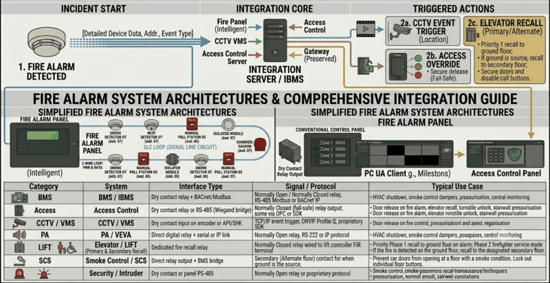
Fire alarm integration is fundamentally a life safety issue, not just a technical checkbox. When a fire is detected, the building needs to do several things simultaneously and in the correct sequence:
- Alert occupants through sounders and voice evacuation announcements
- Shut down HVAC systems to prevent smoke from spreading through ductwork
- Activate smoke control systems to maintain tenable conditions on escape routes
- Release magnetically held fire doors to compartmentalise the fire
- Recall lifts to the ground floor to prevent occupants from using them during evacuation
- Unlock access-controlled fire exits so people can evacuate without delay
- Trigger CCTV recording and camera pop-up so the control room can verify the alarm and monitor evacuation
- Notify the building management system for remote monitoring and fault logging
None of these actions happen automatically unless the integration has been designed, wired, programmed, and tested. A fire alarm system that operates in isolation — even a perfectly designed addressable system — cannot do any of the above without deliberate integration work.
In BS 5839-1 terms, the cause-and-effect relationships between the fire alarm and other building systems are part of the system design and must be documented, reviewed by the consultant, and tested during commissioning. Under NFPA 72, the same requirements are captured in the system operational program and the Record of Completion. Either way, integration is a standard requirement .
Understanding the Interface Types
Before diving into each system individually, it helps to understand the two fundamental ways fire alarm panels communicate with other systems. Getting this right at design stage prevents the most common integration failures.
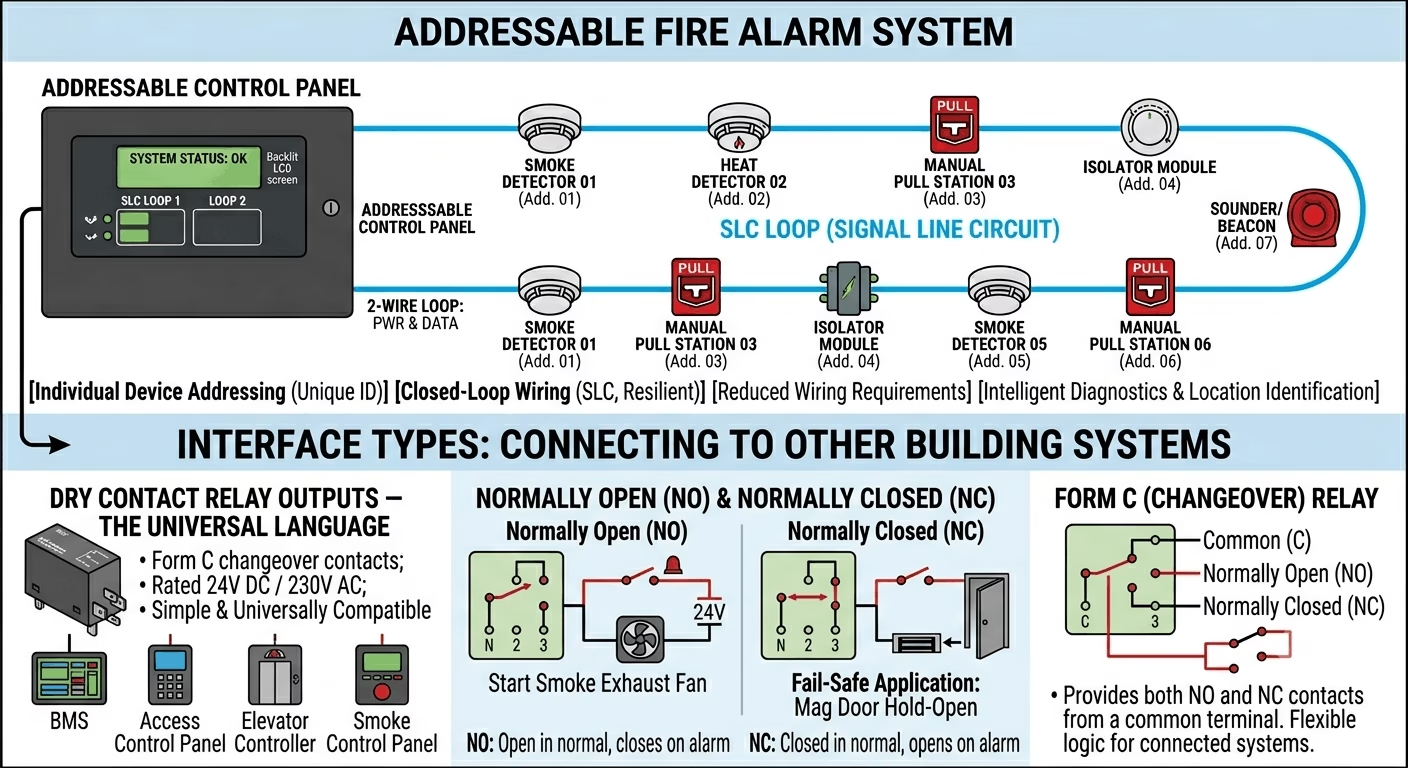
Dry Contact Relay Outputs — The Universal Language
Most fire alarm panels provide a set of programmable relay outputs — typically Form C (changeover) contacts rated at 24V DC or 230V AC, 2A or 5A depending on the panel. These relays are the simplest and most universally compatible interface method. Every BMS, access control panel, elevator controller, and smoke control panel in the world can accept a dry contact input.
Normally Open (NO): The relay contact is open in normal (non-alarm) state and closes on alarm. Used when the connected system needs a closed circuit to trigger an action — for example, starting a smoke exhaust fan.
Normally Closed (NC): The relay contact is closed in normal state and opens on alarm. Used for fail-safe applications — for example, magnetic door hold-opens that must release (fail open) when power or the relay signal is lost.
Form C (Changeover): The relay provides both NO and NC contacts from a common terminal. The most flexible option — use whichever contact logic the connected system requires.
| Critical Design Point
Always design relay interfaces using fail-safe logic where life safety is involved. A magnetic door hold-open that keeps a fire door open during normal use MUST use a Normally Closed (NC) or Form C relay — so that the door releases (closes) on both fire alarm activation AND power failure. A Normally Open relay that only releases the door on alarm but stays open on power failure is a life safety violation. |
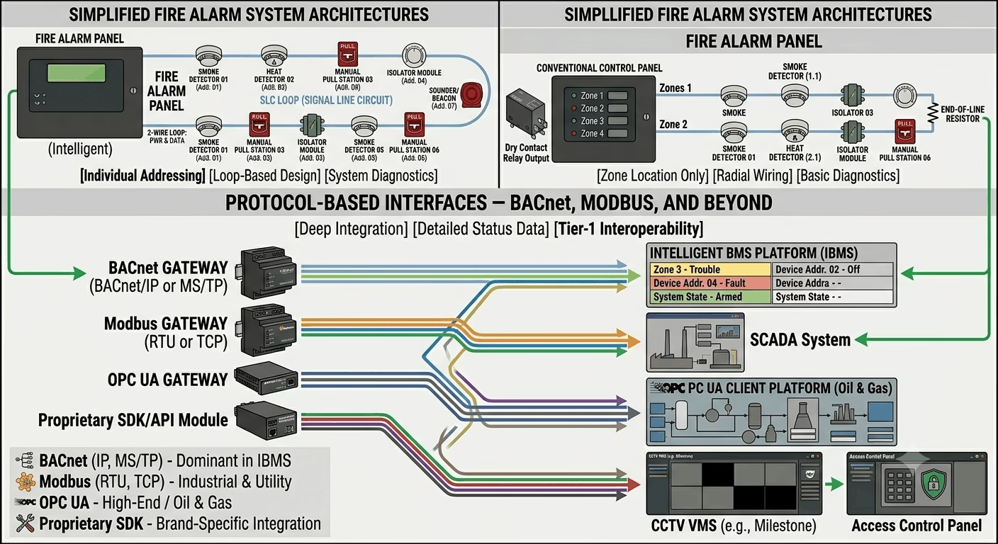
Protocol-Based Interfaces — BACnet, Modbus, and Beyond
For more sophisticated integration — particularly with intelligent BMS platforms — fire alarm panels increasingly support protocol-based communication. This allows the BMS to receive not just a binary alarm/no-alarm signal, but detailed zone-by-zone status, device-level fault information, and system state data.
- BACnet/IP or BACnet MS/TP — the dominant protocol in modern IBMS environments. Many tier-1 fire alarm panels (Siemens Sinteso, Notifier NFS2-3030, Hochiki ESP) support BACnet gateways.
- Modbus RTU / Modbus TCP — widely used in industrial and utility environments. Simpler than BACnet but less expressive.
- OPC UA — used on some high-end integrated building platforms, particularly in oil & gas and petrochemical facilities.
- Proprietary SDK/API — some CCTV VMS platforms and access control systems offer proprietary integration modules that communicate directly with specific fire alarm panel brands.
| ⚠ Protocol Compatibility Warning
Not all fire alarm panels support protocol-based interfaces out of the box. Many require an additional gateway module that adds cost and complexity. Confirm protocol support — and the specific firmware version required — with the panel manufacturer before specifying BACnet or Modbus integration in your design. A relay-based interface, while simpler, is always available as a fallback. |
The table below summarises the standard interface method, signal type, and use case for each integrated system:
| System | Interface Type | Signal / Protocol | Typical Use Case |
| BMS / IBMS | Dry contact relay + BACnet/Modbus | Normally Open / Normally Closed relay; RS-485 Modbus or BACnet IP | HVAC shutdown, smoke control dampers, pressurisation, central monitoring |
| Access Control | Dry contact relay or RS-485 (Wiegand bridge) | Normally Closed (fail-safe) relay output; some via OPC or SDK | Door release on fire alarm, elevator recall, turnstile unlock, stairwell pressurisation |
| CCTV / VMS | Dry contact input on encoder or API/SDK | TCP/IP event trigger, ONVIF Profile Q, proprietary SDK | Alarm-triggered recording, camera pop-up on workstation, PTZ pre-position |
| PA / VEVA | Direct digital relay + serial or IP link | Normally Open relay; RS-232 or IP protocol | Zoned voice evacuation, phased evacuation messages, all-call alert |
| Elevator / Lift | Dedicated fire recall relay | Normally Closed relay wired to lift controller FIR terminal | Phase 1 recall to ground floor on alarm; Phase 2 firefighter service mode |
| Smoke Control / SCS | Direct relay output + BMS bridge | Normally Open relay; BACnet or LON in larger IBMS | Smoke exhaust fan start, supply fan stop, damper open/close by zone |
| Security / Intruder | Dry contact or panel RS-485 | Normally Open relay or proprietary protocol | Arm/disarm on building status; siren integration; guard tour abort on alarm |
Integration 1 — Fire Alarm and BMS (Building Management System)
The BMS integration is typically the most complex and the most critical to get right. On a modern commercial or institutional building, the BMS is responsible for HVAC control, energy management, and central monitoring — and fire alarm events need to drive multiple BMS actions simultaneously.
What the BMS Needs from the Fire Alarm
- A general fire alarm relay output — confirming the system is in alarm state
- Zone-by-zone alarm outputs — so the BMS can take localised actions (e.g. shut only the AHU serving the alarm floor rather than the entire building)
- A fault relay output — so BMS operators receive notification of fire alarm system faults
- A system reset input — some BMS platforms monitor whether the fire alarm has been reset after an event
What the Fire Alarm Typically Triggers in the BMS
Typical cause-and-effect actions driven by the fire alarm panel through the BMS interface include:
- AHU (Air Handling Unit) shutdown — all supply and return air handling units serving the alarm zone are stopped to prevent smoke spread through ductwork
- Smoke control activation — smoke exhaust fans are started and smoke dampers in the affected zone open; pressurisation fans for stairwells and lobbies are activated
- Fire damper release — fire/smoke combination dampers in ductwork are commanded to close via the BMS when the fire alarm is activated in their zone
- Chiller plant protection — in some specifications, chiller plants are commanded to safe shutdown on general fire alarm to protect equipment during emergency ventilation mode
- Central monitoring alert — the BMS generates a high-priority alarm on the operator workstation, logging the time, zone, and device that initiated the alarm
Wiring the BMS Interface
The most reliable BMS interface uses dedicated relay output modules on the fire alarm panel — one relay per BMS action point, or a common alarm relay plus zone relays as required. Cable from the fire alarm relay terminals to the BMS DDC (Direct Digital Controller) panel input terminals.
Specify fire-rated LSZH cable for all fire alarm interface wiring, even where the cable enters the BMS panel. The circuit must maintain integrity during fire conditions to ensure BMS actions continue to operate throughout the emergency.
| Field Note — BMS Coordination Meeting
On every project I manage, I hold a dedicated BMS coordination meeting early in the construction phase with the fire alarm engineer, BMS engineer, and mechanical engineer present. The output is a joint cause-and-effect schedule that everyone signs off on. Without that meeting, you will discover conflicts between the fire alarm cause-and-effect logic and the BMS control sequences at commissioning — and untangling them costs days, not hours. |
Integration 2 — Fire Alarm and Access Control
The interface between fire alarm and access control is the one that most directly affects people’s safety during an evacuation. If it is not designed correctly, occupants can find themselves unable to exit the building during a fire — which is not just a compliance failure but potentially a fatal one.
The Core Requirement — Fail-Safe Door Release
Every access-controlled door on a designated fire escape route must release automatically on fire alarm activation. This is a non-negotiable requirement under BS 5839-1, NFPA 72, NFPA 101, and virtually every local building code in the world.
The release must be fail-safe — meaning the door releases not only when the fire alarm activates, but also when power fails. This rules out Normally Open relay logic for magnetic locks. The correct approach:
- Magnetic locks (maglocks) on fire escape routes must be wired as Normally Closed (power-to-lock, fail-safe). They release when the fire alarm relay opens OR when power is lost.
- Electric strikes on fire doors can use Normally Open logic only if a separate mechanical free-egress function (push-bar/thumb-turn release) is provided, confirming with the local fire authority.
- Electromagnetic door hold-opens (devices that hold fire doors open during normal use) must release on fire alarm activation via Normally Closed relay.
Access Control Panel Interface Methods
There are three common methods for interfacing fire alarm with access control:
Method 1 — Direct Relay to Maglock: The fire alarm panel relay output is wired directly in series with the maglock power supply. On alarm, the relay opens, cutting power to all maglocks on that circuit. Simple and reliable, but limited to coarse control — all locks on the relay output release simultaneously.
Method 2 — Relay to Access Control Panel Input: The fire alarm panel relay output connects to a dedicated fire alarm input on the access control panel. The access control panel then executes a pre-programmed action plan — releasing specific doors, locking others, overriding access schedules. More flexible but requires careful programming coordination.
Method 3 — Protocol Integration: Some access control platforms (Lenel S2, Genetec, CCURE 9000, Gallagher) support direct protocol-based integration with specific fire alarm panel brands. This allows zone-by-zone door release actions driven by granular fire alarm data, and fire alarm events visible on the access control operator screen.
Elevator (Lift) Recall — Phase 1 and Phase 2
Lift recall is technically an access control and life safety function that is driven by the fire alarm system. It is worth covering here because the interface is frequently missed or misunderstood on first-time projects.
- Phase 1 Recall: On fire alarm activation, all lifts are recalled to the designated ground floor (or alternative refuge floor if ground floor is the fire floor). Lift doors open and remain open. The fire alarm panel drives this via a dedicated Normally Closed relay to the lift controller FIR (Fire Input Relay) terminal.
- Phase 2 Firefighter Service: Allows the fire service to use individual lifts under manual control for firefighting operations. This is typically a key-switch function at the lift itself — not driven by the fire alarm panel directly, but requires coordination with the lift supplier to confirm FIR terminal wiring spec.
| ⚠ Critical — Confirm Lift Interface Early
Lift suppliers are notorious for providing their FIR terminal wiring specification late in the project. I have seen projects delayed at final commissioning because the lift FIR input required a 24V DC signal and the fire alarm panel was providing a volt-free relay contact — incompatible without an additional interface relay. Confirm the lift controller FIR specification from the supplier at design stage, before the fire alarm panel is programmed. |
Integration 3 — Fire Alarm and CCTV / VMS
CCTV integration with the fire alarm system is increasingly standard on commercial, retail, hospitality, and critical infrastructure projects. The purpose is straightforward: when the fire alarm activates, the security team in the control room needs immediate visual confirmation of the alarm location so they can verify whether it is a genuine fire or a false alarm, and monitor the evacuation.
What Good CCTV Integration Looks Like
- Camera pop-up on the VMS workstation — cameras covering the alarm zone automatically appear on the operator screen without manual intervention
- Alarm-triggered recording — cameras in the alarm zone switch to continuous high-frame-rate recording on alarm activation, overriding normal motion-triggered recording schedules
- PTZ pre-position — PTZ cameras covering the alarm area are automatically commanded to a pre-configured preset that covers the most likely evacuation routes or fire risk areas
- Alarm event log synchronisation — the fire alarm event timestamp is logged in the VMS alarm database alongside the corresponding video footage, creating a unified incident record for post-event investigation
Interface Methods for CCTV Integration
Method 1 — Dry Contact Input on Camera or NVR: Many NVRs and IP cameras provide alarm input terminals. A fire alarm relay connects to these terminals. On alarm, the camera or NVR triggers pre-programmed actions including recording start and PTZ preset. Simple to configure but limited in sophistication.
Method 2 — VMS Alarm Input Module: Most enterprise-grade VMS platforms (Milestone XProtect, Genetec Security Centre, Hikvision iVMS, Dahua DSS) include alarm input modules. The fire alarm relay connects to an alarm input on a hardware interface module, and the VMS handles all downstream actions including pop-up, recording, and PTZ. More flexible and centralised.
Method 3 — Protocol / API Integration: Some fire alarm panels and VMS platforms support direct API or SDK integration, allowing the VMS to receive zone-level alarm data rather than just a binary contact closure. This enables camera grouping by zone so that only cameras relevant to the alarm area are triggered, rather than all cameras simultaneously.
Configuring CCTV Integration — Practical Steps
- Map every fire alarm zone to the CCTV cameras that cover that area. Create a zone-to-camera matrix and include it in the cause-and-effect documentation.
- Programme the VMS alarm input to trigger on closure of the fire alarm relay output designated for CCTV integration.
- Configure camera actions in the VMS: which cameras pop up, which PTZ presets activate, what recording profile switches to on alarm.
- Test each zone individually during commissioning. Activate a detector in Zone 1 and verify that only the Zone 1 cameras trigger. Repeat for all zones.
- Ensure the VMS operator screen layout is configured to show alarm zone cameras in a prominent window — not buried in a multi-screen grid that an operator might miss.
| Practical Tip — CCTV Coverage Gaps
During the fire alarm zone-to-camera mapping exercise, you will sometimes discover that a fire alarm zone is not adequately covered by any CCTV camera. Flag this to the client early. A fire alarm activation in an uncovered area still triggers an alarm on the control room screen, but the operator has no visual to verify it. On high-risk projects (data centres, hospitals, warehouses), additional cameras are justified purely on the basis of fire verification coverage. |
Integration 4 — Fire Alarm and PA / Voice Evacuation (PAVA)
On any building above a certain complexity threshold — multi-storey offices, shopping malls, hospitals, hotels, airports — a simple sounder is not sufficient for evacuation. Voice evacuation systems give you the ability to deliver specific, intelligible messages to specific zones, enabling phased or staged evacuation rather than a building-wide simultaneous evacuation.
Phased Evacuation — Why It Matters
A simultaneous full-building evacuation in a 30-storey tower creates dangerous congestion on stairwells. Phased evacuation addresses this by initially evacuating only the fire floor and the two floors immediately above and below, while placing other floors on an alert status. As the situation develops, additional floors are evacuated in sequence.
This is a fire strategy decision that must be agreed with the fire authority and the consultant at the design stage. The fire alarm cause-and-effect logic must then implement the phased evacuation sequence precisely — and it must be coordinated between the fire alarm panel, the PAVA controller, and the BMS.
The Fire Alarm to PAVA Interface
The interface between the fire alarm panel and the PAVA system typically uses dedicated relay outputs on the fire alarm panel connected to alarm inputs on the PAVA controller. The PAVA controller is pre-programmed with evacuation message sequences triggered by these inputs.
On more sophisticated installations, the fire alarm panel communicates with the PAVA controller via a serial (RS-232) or IP link, sending zone identification data that allows the PAVA to select the correct phased evacuation message sequence automatically.
- Alarm input relay — fire alarm relay triggers pre-recorded evacuation message playback on designated speaker zones
- Zone identification relay bank — one relay per floor or zone, allowing the PAVA to identify the alarm location and play the correct phased message
- Fault monitoring — the fire alarm panel can monitor the PAVA system for faults via a return fault relay from the PAVA controller
| BS EN 60849 Note
Voice alarm systems in the UK and GCC are governed by BS EN 60849 (Sound systems for emergency purposes). This standard requires that the VA system provides intelligible speech at a minimum of 65 dB(A) at 1 metre from any sounder, or 10 dB(A) above the ambient noise level in the space. Coordination between the fire alarm engineer and the PA/VA system designer is essential to ensure message intelligibility is verified during commissioning testing. |
Integration 5 — Fire Alarm and Smoke Control Systems
Smoke is responsible for the majority of fire fatalities — not flame. Smoke control integration with the fire alarm system is therefore one of the most life-critical interfaces in the entire building, and it deserves the most careful design attention.
Types of Smoke Control Systems and Their Fire Alarm Interface
Natural Ventilation (AOV — Automatic Opening Vents): Roof vents or high-level windows that open automatically on fire detection to allow smoke to escape under buoyancy. Driven by direct relay output from the fire alarm panel to the AOV control panel. AOVs in stairwells and atria are the most common application.
Mechanical Smoke Exhaust: Dedicated extract fans that activate on fire alarm to remove smoke from the fire floor or compartment. The fire alarm panel triggers fan start via relay to the MCC (Motor Control Centre) or direct to the BMS, which commands the fan VSD or starter.
Pressurisation Systems: Supply fans that pressurise stairwells, lobbies, and firefighting shafts to prevent smoke ingress. Activated by fire alarm relay output on detection of alarm in any zone. Essential for high-rise buildings and designated firefighting shafts.
Smoke/Fire Dampers in Ductwork: Fire dampers that close on activation of a fusible link or motorised actuator signal. In sophisticated HVAC systems, zone-specific damper control is driven by the BMS using fire alarm zone relay inputs to determine which dampers to close.
| ⚠ Smoke Control Coordination with Mechanical Engineer
Smoke control system design is typically the responsibility of the mechanical engineer or a specialist smoke control consultant. The fire alarm engineer’s role is to provide the correct relay outputs at the fire alarm panel and to coordinate the cause-and-effect logic with the mechanical design. Miscoordination — for example, a pressurisation fan that activates when it should not, or a smoke exhaust fan that does not start on alarm — can invalidate the fire engineered solution and require re-commissioning of the entire mechanical smoke control system. |
The Cause-and-Effect Matrix
Every integrated fire alarm project needs a cause-and-effect (C&E) matrix. This is a document — typically a spreadsheet or table — that maps every possible fire alarm input (cause) to every output action (effect) across all integrated systems. It is the single most important coordination document on the project.
The cause-and-effect matrix must be:
- Prepared by the fire alarm engineer in coordination with the BMS, access control, CCTV, PA, and mechanical engineers
- Reviewed and signed off by the lead consultant before commissioning begins
- Included in the O&M manual and as-built documentation package
- Used as the test script during integration commissioning — every row in the matrix is tested and the result recorded
Here is a simplified example of a cause-and-effect matrix for a multi-storey commercial building:
| Trigger (Cause) | Zone / Location | BMS Action | Access Control | CCTV Action |
| Single detector alarm | Floor 3 — Office | Notify BMS; no HVAC action | No door release | Pop-up cameras Floor 3 |
| Confirmed alarm (2 detectors) | Floor 3 — Office | Shut AHU Floor 3; open smoke exhaust | Release all Floor 3 fire doors | Start recording; PTZ to stairwell |
| Manual Call Point | Floor 3 — MCP near lift | Shut all AHUs; open full exhaust | Release all doors building-wide; recall lifts | Full building camera recording |
| Alarm — Car Park | B1 Car Park | Activate car park exhaust fans; close fire dampers | Open all car park exits; raise barriers | Record all car park cameras; pop-up at workstation |
| Fault — Any Zone | System-wide | Send fault signal to BMS | No change | No change |
| System Reset | All zones | Restore BMS normal mode | Restore normal access schedule | Stop triggered recordings; restore normal |
| Field Note
I have worked on projects where the cause-and-effect matrix was prepared for the first time during commissioning — which meant the first time anyone discovered a conflict between the fire alarm logic and the BMS control sequence was in front of the client. Prepare the C&E matrix at RIBA Stage 4 (technical design), not Stage 5 (construction). Every hour spent resolving it on paper saves a day of rework on site. |
Step-by-Step: How to Manage Fire Alarm Integration on Your Project
Based on over 15 years of integrated ELV project delivery across the GCC, here is the workflow I follow on every project where fire alarm integration is required:
Step 1 — Identify All Integration Requirements at Design Stage
Review the project specification and building services drawings. List every system that the fire alarm must interface with: BMS, access control, CCTV, PA/VEVA, lifts, smoke control. Confirm this list with the lead consultant and MEP coordinator. Add any missing interfaces to the fire alarm specification before the contract is let.
Step 2 — Hold an Integration Coordination Meeting
Bring together the fire alarm engineer, BMS engineer, access control contractor, CCTV installer, PA system designer, lift supplier, and mechanical engineer. The agenda: agree the interface method for each integration point, confirm relay contact ratings, agree cable routing and termination responsibilities, and assign who produces the cause-and-effect matrix.
Step 3 — Confirm Panel Relay Output Capacity
Count the total number of relay outputs required across all integrations. A typical commercial project with BMS, access control, CCTV, and smoke control integration requires between 15 and 40 relay outputs depending on zone count. Many standard fire alarm panels provide only 4–8 relay outputs as standard. Order relay expander modules early — they have long lead times on some panel brands.
Step 4 — Produce and Agree the Cause-and-Effect Matrix
Draft the C&E matrix covering all input triggers (zone alarm, general alarm, fault, reset) and all output actions per integrated system. Circulate to all parties for review. Resolve conflicts before programming begins. Get written sign-off from the consultant — this becomes the commissioning test script.
Step 5 — Programme and Wire the Interfaces
Programme all relay output logic in the fire alarm panel per the agreed C&E matrix. Run interface cables from the fire alarm panel relay terminals to each connected system panel. Label every cable at both ends with the interface reference from the C&E matrix (e.g. FA-BMS-R01, FA-ACS-R03). Use fire-rated LSZH cable throughout.
Step 6 — Pre-Commission Each Interface Individually
Before full system integration testing, test each interface point individually. Activate a relay on the fire alarm panel and verify the connected system responds correctly. For BMS — confirm the correct AHU shuts down. For access control — confirm the correct door releases. For CCTV — confirm the correct cameras pop up.
Step 7 — Conduct Full Integration Commissioning Test
With all systems operational, conduct a row-by-row test of the cause-and-effect matrix. Activate each trigger scenario (single detector alarm, confirmed alarm, MCP activation, fault) and verify all output actions fire correctly and simultaneously. Record results on the commissioning test sheet, signed by the engineer and witnessed by the consultant.
Step 8 — Prepare the Integration Handover Package
Compile the following documents for the O&M manual:
- Signed cause-and-effect matrix (as-tested version)
- Interface wiring diagrams showing terminal numbers at both fire alarm panel and connected system panels
- Panel relay output schedule — which relay number does what, and which zone it corresponds to
- Integration commissioning test records with pass/fail results for every interface point
- Maintenance instructions for each interface — particularly which relay outputs to test during annual service
Common Integration Mistakes to Avoid
These are the integration failures I see repeatedly on site. All of them are avoidable with proper coordination:
Using Normally Open relay logic for magnetic locks on fire escape routes — the locks stay locked on power failure, trapping occupants. Always use fail-safe Normally Closed logic.
- Not confirming lift FIR terminal specification with the lift supplier before panel programming — the FIR may require a voltage signal, not a volt-free contact.
- Specifying BACnet integration without confirming the fire alarm panel firmware supports it — many panels need a paid gateway module that was not in the original BOQ.
- Producing a cause-and-effect matrix in isolation without the BMS or mechanical engineer reviewing it — conflicts between fire alarm logic and HVAC control sequences are only discovered at commissioning.
- No zone-to-camera mapping for CCTV — all cameras trigger on any alarm, creating chaos on the operator screen and making it impossible to verify the alarm location quickly.
- Running interface cables in non-fire-rated conduit or without LSZH insulation — the interface wiring must maintain circuit integrity during fire conditions.
- Not testing the integration under realistic conditions during commissioning — a relay that works when tested individually sometimes fails to fire correctly when multiple relays activate simultaneously. Always test the full cause-and-effect scenario.
Conclusion — Integration Is Where the System Earns Its Keep
A fire alarm system that does nothing except sound a sounder is a very limited life safety tool. The same system, properly integrated with BMS, access control, CCTV, PA, smoke control, and lifts, becomes the central nervous system of the building’s emergency response — automatically executing the correct sequence of protective actions the moment a fire is detected, before any human intervention.
If you are facing a specific integration challenge on a current project — a BMS protocol mismatch, a lift supplier who cannot provide the FIR spec, a VMS that does not support the relay interface you have specified — post it in the comments on techubox.com. These are exactly the real-world problems this community is built to help with.