
Locking the doors on every floor is pointless if anyone can ride the lift straight to the tenant floors. That is why office towers, hotels, hospitals and residential buildings ask for lift access control: you present a card in the car, and only the floors you are allowed to visit light up. Access control elevator integration sounds simple, but it touches equipment that belongs to the lift company, it must never interfere with fire service operation, and the relay count grows quickly. This guide shows how floor select actually works, how to wire it, when to use a high-level interface instead, and how to count relays for a real 12-stop building.
Quick answer: The common method is low-level integration: a reader in the lift car feeds an access controller, which drives a relay output board. One relay contact is wired in series with each secured floor button in the car operating panel (COP), so the button only works for a few seconds after a valid card. The high-level method connects the access control server to the lift group controller over the network, usually with destination dispatch. In both cases the lift supplier must confirm that fire recall and firefighter service override the access control.
Our earlier article on how to connect access control to the elevator walks through one specific brand’s lift controller and firmware. Here we stay brand-neutral and focus on the design: wiring, fire mode, cabling and the numbers.
What Access Control Elevator Integration Does
There are three levels of control, and a project can use one or several:
- Car call control (floor select): the reader is inside the car. A valid card enables the buttons for the floors that card holder may visit. The most common type.
- Hall call control: a reader at a landing enables the up or down call button on that floor, for example a car park level where only residents may call the lift.
- Destination control: the card is read at a lobby panel or turnstile, and the lift system assigns a car that goes to the card holder’s floor. This needs a high-level interface.
Public floors such as the ground floor lobby, restaurant or gym stay free at all times, and many buildings release all floors during business hours by schedule, securing them only at night and at weekends.
Low-Level vs High-Level Integration
| Item | Low-level (relay boards) | High-level (network interface) |
|---|---|---|
| Connection | Dry contacts in series with each floor button | Ethernet link between access server and lift group controller |
| Hardware | Reader in car, controller, relay boards, optional input boards | Interface licence and gateway on both sides; readers at lobby panels or turnstiles |
| Lift brand dependence | Works with most conventional button panels | Needs the lift maker’s interface, protocol and approval |
| Travelling cable | Extra cores per car | Usually nothing extra in the car |
| Features | Floor enable, timed access, schedules | Floor assignment, default floor per card, VIP or accessible service, better traffic handling |
| Typical use | Retrofits, mid-rise offices, residential, hotels | New high-rise towers with destination dispatch |
My field advice: Before choosing low-level, ask the lift supplier one question: “Are the car buttons discrete wired contacts, or are they on a serial bus?” Many modern COPs send button presses over a serial or CAN-type bus to the controller. There is no simple wire to break, so you need the lift company’s own interface board or a high-level link.
Floor Select Wiring with Relay Output Boards
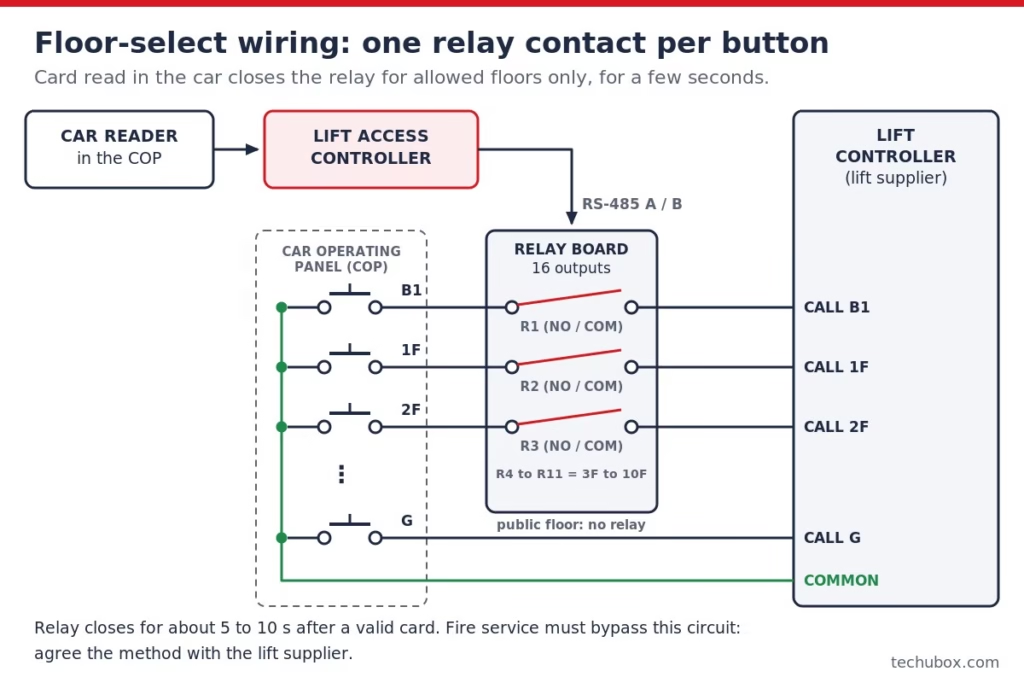
Step by step, for a conventional COP with discrete button wiring:
- Reader in the car. A flush or surface reader in or above the COP. Wiegand (D0/D1) or OSDP (RS-485 A/B) to the controller. The reader cable runs in the travelling cable unless the controller is on the car. For protocols, see Wiegand vs OSDP.
- Lift access controller. A controller or controller mode that supports lift (floor) control. It decides which floors each card may select and for how long.
- Relay output board. Connected to the controller, usually on RS-485 (A/B). Boards commonly come in 8 or 16 outputs. One output per secured floor, per car.
- Series connection. The lift supplier’s button wire runs: controller common → button → relay contact → controller call input. With the contact open, pressing the button does nothing. A valid card closes the relays for that card’s floors for a set time, typically 5 to 10 seconds.
- Public floors. No relay. The button is wired straight through.
- Optional input board (floor tracking). Monitoring the button press tells the access system which floor the user actually chose, not just which floors were enabled. Useful for audit trails in hotels and hospitals.
The button circuit is a low-voltage, low-current signal belonging to the lift controller, so the relays only switch a signal. Still, confirm the voltage and current with the lift supplier and check them against the relay contact rating. Never connect access control power to the lift button circuit.
Which Contact: NO or NC?
This decides what happens when the access controller fails:
- NO contact, relay energised on card (fail-secure): if the controller or relay board loses power, all secured floors stay locked. Common in residential and hotels where security matters most.
- NC contact, relays held energised in normal (fail-safe for floors): the energised relays hold the button circuits open. A valid card de-energises the relays for allowed floors. If power fails, all floors become free. Preferred where users must never be stuck without floor access, such as hospitals.
Whichever you pick, write it in the design and agree it with the client. Some controllers support both modes; check the manual.
Pro tip: Label each relay with car, floor and button wire number inside the board. Lift technicians will open your enclosure one day during a breakdown, and clear labels stop them cutting your wiring out “to get the lift running”.
High-Level Integration with the Lift Controller
In a high-level integration the access control server and the lift group controller exchange data over the network. The card is read at a lobby destination panel, a turnstile or a reader near the lift lobby. The access system tells the lift system which floors that card may use (and often a default floor), and the lift system allocates a car. Nothing is wired into the car buttons.
What to prepare:
- The lift maker’s interface specification, licence and a list of approved access control partners. Each lift company has its own interface, and not every access system supports every lift brand.
- A network connection between the two systems, usually through a firewall or dedicated VLAN. Agree who owns it.
- A floor and door naming scheme shared by both systems, including mezzanines and car park levels.
- The failure mode: what the lift system does if the access server is offline (all floors free, or secured floors locked).
High-level costs more in licences and coordination, but it removes travelling cable work, scales to dozens of cars and enables features relay boards cannot, such as sending wheelchair users to a car with more time at the doors.
Fire Mode, Recall and Homing
This is the part that must never go wrong. During a fire, the lifts follow their own safety logic, driven directly by the fire alarm system and the lift controller, not by access control.
- Fire recall (Phase I in ASME A17.1 terms; EN 81-73 in Europe): on a fire signal, lifts return to the designated floor (or an alternate floor if the fire is on the main floor), open their doors and are taken out of normal service. Car calls are cancelled by the lift controller.
- Firefighter service (Phase II; firefighters lifts to EN 81-72): firefighters operate a lift with a key switch and must be able to select any floor. If your relays still block secured floor buttons at this point, you have created a life safety hazard.
- Homing (parking): in normal service an idle lift may return to a home floor such as the lobby. This is lift controller logic; just make sure your schedules do not lock the home floor’s button.
How to make sure access control steps aside:
- The fire alarm signal for recall goes from the fire panel directly to the lift controller, never through the access control system. See our access control and fire alarm integration guide for the door side of the same alarm.
- The lift supplier provides a bypass so that in firefighter service the access control enable circuit is ignored. Ask how they do it: some route your contacts only in normal mode, others provide a bypass contact you wire in parallel with your relays.
- As a second layer, give the access controller a fire input that releases all floors. Do not rely on it alone.
- Test it: put the building in fire alarm, check recall, then switch a car to firefighter service and press every secured floor without a card.
Follow the lift standard and the local authority on the project; in Saudi Arabia, Civil Defense reviews lift fire operation during final inspection, so get the lift supplier’s fire mode description in writing early.
Practical Example: Relay Count for a 12-Stop Building
An office tower with 12 stops: B1 car park, G lobby and offices on 1F to 10F. Two passenger lifts (A and B) and one service lift (S) serve every stop. The lobby is public. B1 and all office floors need a card.
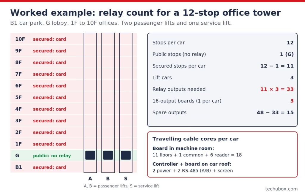
Step 1: secured stops per car. 12 stops − 1 public stop (G) = 11 secured stops.
Step 2: relay outputs. 11 relays per car × 3 cars = 33 relay outputs. Every car needs its own set, because each COP has its own buttons.
Step 3: boards. With 16-output boards, one board per car covers 11 floors: 3 boards, 48 outputs, 15 spare. Keep the spares; a future mezzanine or a “floor released” status output will use them. With 8-output boards you would need 2 per car (6 boards), so the 16-output board is simpler here.
Step 4: floor tracking (optional). If the client wants to log which floor was pressed, add 11 inputs per car: 33 inputs, again 3 boards of 16.
Step 5: travelling cable cores. This is where projects get stuck.
- Relay board in the machine room: 11 floor wires + 1 common + about 6 reader cores (+12 V, 0 V, D0, D1, LED, buzzer) = 18 cores per car in the travelling cable. The lift supplier rarely has that many spare.
- Controller and relay board in an enclosure on the car roof: 2 power cores + 2 RS-485 or a network pair, plus screen = about 4 or 5 cores per car. The floor wiring stays inside the car. This is usually the better option, if the lift supplier allows equipment on the car roof.
Step 6: power. Each car-roof enclosure needs a small 12 V DC supply with battery. Relay board, controller and reader together typically draw well under 1 A (check datasheets). Size the standby with the Battery Backup Calculator.
You can add the lift readers and relay boards to the rest of the building design in the Access Control Designer, and the bigger picture of planning is in how to design an access control system.
Coordination Checklist with the Lift Supplier
| Question | Why it matters |
|---|---|
| Are COP buttons discrete wired or on a serial bus? | Decides relay vs interface board vs high-level |
| Button circuit voltage and current | Relay contact rating |
| Spare cores or data pair in the travelling cable | Machine room vs car-roof design |
| Space and permission for an enclosure on the car roof or in the COP | Where the reader, controller and boards live |
| How firefighter service bypasses the access circuit | Life safety, Civil Defense inspection |
| Who terminates inside the COP | Warranty; most lift companies insist on doing it themselves |
Troubleshooting Lift Access Control
| Symptom | Likely cause | Fix |
|---|---|---|
| Card accepted but no floor button works | Relay board offline (RS-485 address or wiring), or wrong board mapped | Check board address, A/B polarity, termination and mapping in software |
| Wrong floor enabled | Relay to floor mapping swapped | Test each floor with a test card; correct the mapping table |
| All floors free even after hours | Schedule still in “office hours” mode, or controller time wrong | Check schedules and NTP time on the controller |
| Buttons blocked in firefighter service | No bypass from lift controller | Stop and fix with lift supplier before handover |
| Intermittent reads in the car | Reader cable in travelling cable next to motor or door operator wiring | Use a screened cable or move the controller onto the car |
| Floor only enabled for a moment | Enable time too short | Increase to around 5 to 10 s |
For the camera side of lift lobbies and cars, see access control and CCTV integration. If the lift itself stops answering, our no response from lift control panel note may help.
Frequently Asked Questions
How many relays do I need for lift access control?
One relay output per secured floor, per lift car. A 12-stop building with one public floor and three cars needs 11 × 3 = 33 outputs, typically three 16-output boards.
Can access control be added to an existing lift?
Usually yes, if the car buttons are discrete wired contacts and there are spare travelling cable cores or room for an enclosure on the car. If the buttons are on a serial bus, you need the lift supplier’s interface.
What happens to lift access control in a fire?
The fire alarm signals the lift controller directly, and the lifts return to the designated floor. In firefighter service the firefighters must be able to select every floor, so the lift controller must bypass the access control circuit.
What is the difference between low-level and high-level lift integration?
Low-level uses relay contacts in series with each floor button. High-level uses a network interface between the access control server and the lift group controller, often with destination dispatch, and needs the lift maker’s protocol and licence.
Should lift relays be fail-safe or fail-secure?
It is a client choice. Fail-secure (NO contacts) keeps floors locked if access control fails. Fail-safe (NC contacts, relays held energised) frees all floors on failure. Hospitals often choose fail-safe; residential and hotels often choose fail-secure.
Do I need a separate reader for each lift car?
For car call control, yes: one reader per car, because the floors are enabled on that car’s buttons only. With destination dispatch, the readers are at lobby panels or turnstiles instead.