
CCTV Installation & Wiring Guide
HD Analog and IP Cameras from Beginner to Advanced & 60-Camera DIY Project
Whether you are putting four cameras on your villa or planning a 60-camera warehouse system, every CCTV job comes down to the same three things: the right camera, the right cable, and the right recorder. This guide walks you through all three in plain language first, then goes deeper for engineers and advanced DIYers. At the end you will find a complete, real-world 60-camera IP project you can follow step by step.
How to use this guide
-
Beginner: read Parts 1 to 4 and the DIY steps in Part 6.
-
Intermediate: focus on the wiring schematics in Parts 4 and 5, and the calculations.
-
Advanced: jump to Part 8 (network design, VLANs, cybersecurity) and Part 9 (the 60-camera project).
Part 1: CCTV Terminology You Must Know
|
Term |
What it means in simple words |
|
CCTV |
Closed-Circuit Television: cameras that record to your own recorder, not broadcast publicly. |
|
HD Analog |
Modern analog cameras that send HD video over coaxial cable. Formats: HD-TVI, HD-CVI, AHD. |
|
IP Camera |
A network camera. It compresses video itself and sends it over Ethernet (Cat6) like a computer. |
|
DVR |
Digital Video Recorder. Records analog cameras over coax. |
|
XVR / HVR |
Hybrid recorder. Accepts HD analog and some IP cameras. |
|
NVR |
Network Video Recorder. Records IP cameras over the network. |
|
Coax (RG59 / RG6) |
Round 75-ohm video cable used for analog cameras. RG59 is standard for CCTV. |
|
Siamese cable |
RG59 coax and a 2-core power cable (usually 18 AWG) joined together. One pull gives video + power. |
|
BNC connector |
The twist-lock connector on coax cables for analog cameras and DVRs. |
|
Video balun |
A small adapter that lets you send analog video over Cat5e/Cat6 instead of coax. |
|
PoC |
Power over Coax. Video and power on one coax cable, with a PoC-capable DVR. |
|
UTP / Cat6 |
Twisted-pair network cable used for IP cameras. Maximum 100 m per run. |
|
RJ45 |
The 8-pin plug on network cables. |
|
PoE |
Power over Ethernet. The switch or NVR powers the camera through the same Cat6 cable. |
|
802.3af / at / bt |
PoE standards: af = 15.4 W per port, at (PoE+) = 30 W, bt (PoE++) = 60 W or 90 W. |
|
PoE budget |
The total watts a switch can deliver to all ports together. |
|
Switch |
Network device that connects cameras, NVR and other equipment. |
|
SFP / Uplink |
A slot on a switch for fiber modules, used to connect switches over long distances. |
|
VLAN |
A virtual network that separates camera traffic from office traffic on the same switches. |
|
ONVIF |
Open standard so IP cameras and NVRs from different brands work together (Profiles S, G, T). |
|
RTSP |
Streaming protocol used to pull video from a camera into software or an NVR. |
|
H.264 / H.265 / H.265+ |
Video compression. H.265 uses roughly half the bandwidth and storage of H.264. |
|
Bitrate |
How much data a camera sends per second (Mbps). Drives bandwidth and storage. |
|
Main stream / Sub stream |
High-quality stream for recording, low-quality stream for live view on phones. |
|
Focal length (mm) |
Lens size. 2.8 mm = wide view, 6 mm = narrower and more detail, varifocal = adjustable. |
|
FOV |
Field of view: how wide the camera sees. |
|
DORI |
Detect, Observe, Recognise, Identify: image detail levels at 25, 62, 125 and 250 pixels per metre. |
|
IR range |
How far the camera sees in total darkness using infrared LEDs. |
|
WDR |
Wide Dynamic Range. Handles bright doorways and windows without dark faces. |
|
IP66 / IP67 |
Weather protection rating for outdoor cameras (dust and water). |
|
IK10 |
Vandal-resistance rating, important for low-mounted domes. |
|
NVR channels |
Maximum number of cameras the NVR supports (8, 16, 32, 64, 128). |
|
Incoming bandwidth |
Maximum total camera bitrate an NVR can record (for example 320 Mbps). |
|
RAID 5 / 6 |
Hard drive protection. One (RAID 5) or two (RAID 6) drives can fail without losing recordings. |
|
UPS |
Uninterruptible Power Supply. Keeps cameras and NVR recording during power cuts. |
|
MDF / IDF |
Main and intermediate distribution frames: the main rack and the smaller field racks. |
Part 2: HD Analog vs IP Cameras
How HD analog works
The camera captures the image and sends uncompressed HD video down a coax cable. Power comes separately (12 V DC) or over the same coax (PoC). The DVR compresses and records the video.
How IP works
The camera captures, compresses (H.265) and streams the video over Ethernet. One Cat6 cable carries video, power (PoE) and control. The NVR records the streams it receives through the network.
Quick comparison
|
Feature |
HD Analog (TVI/CVI/AHD) |
IP Camera |
|
Typical resolution |
2 MP to 8 MP |
2 MP to 12 MP and higher |
|
Cable |
RG59 coax (or Cat6 with baluns) |
Cat6 UTP |
|
Power |
Separate 12 V DC or PoC |
PoE from switch or NVR |
|
Max distance per run |
Often 300 m+ on coax for 1080p (check datasheet) |
100 m on copper, unlimited with fiber |
|
Smart features (AI, LPR, face) |
Limited |
Full range |
|
Setup difficulty |
Easy, plug and play |
Moderate, needs basic networking |
|
Cost |
Lower |
Higher, but falling |
|
Best for |
Small homes, shops, upgrading old coax |
New builds, businesses, anything above 16 cameras |
My field advice: if the building already has good coax, HD analog is a cheap and solid upgrade. For any new installation, especially above 16 cameras, go IP. It scales better, supports AI analytics, and the wiring is cleaner.
Part 3: Planning Before You Drill a Single Hole
-
Walk the site. Mark every entry, exit, gate, parking area, cash point, corridor and blind corner.
-
Decide what each camera must do. Detect a person at the fence? Recognise a face at the door? Read a number plate at the gate? This decides the lens and resolution (use the DORI levels).
-
Choose camera types.
-
-
Turret / eyeball: indoor and soffit, easy to aim, minimal IR reflection.
-
Dome: low ceilings, vandal-prone areas (choose IK10).
-
Bullet: outdoor walls and poles, visible deterrent, longer IR.
-
PTZ: large open areas, operator-controlled.
-
-
Place the recorder. Central, secure, ventilated, near power and the internet router. Keep every IP camera within 100 m cable length of its switch.
-
Draw a simple layout. Floor plan, camera positions with numbers, cable routes, rack location.
-
Do the maths. Storage, bandwidth, PoE budget and lens. You can use the free Techubox calculators for this.
Part 4: HD Analog Wiring Schematics
4.1 Standard wiring: Siamese cable with central power supply
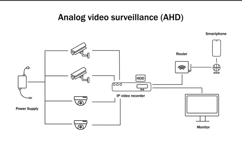
Rules:
-
Use pure copper RG59, not copper-clad aluminium (CCA). CCA causes noise and drops voltage.
-
Crimp or compression BNC connectors only. Avoid twist-on BNCs outdoors.
-
Use a central fused power box (for example 9 or 18 outputs, 12 V DC, 1 A per output).
-
Red = +12 V, black = 0 V. Check polarity before powering up.
4.2 Wiring with video baluns over Cat6
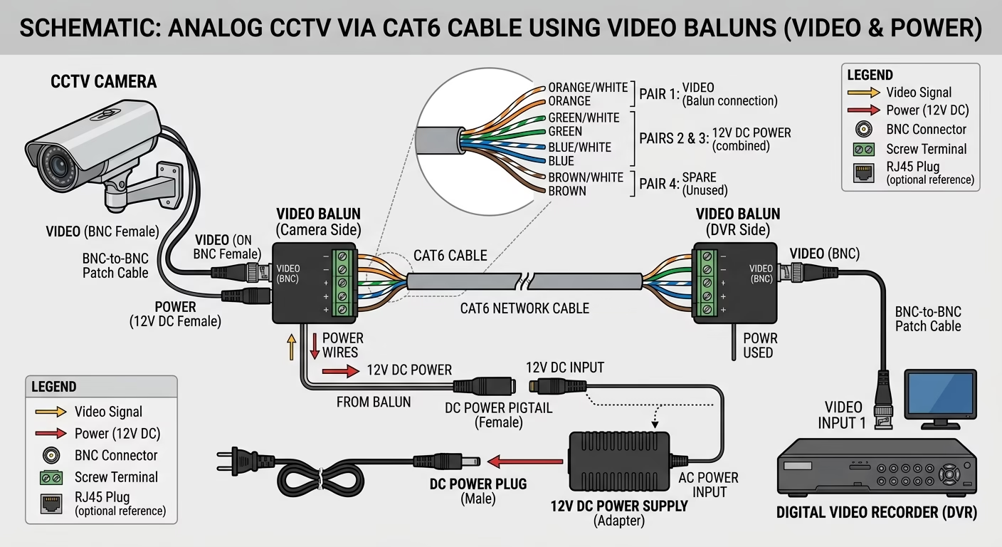
-
One twisted pair carries video. You can use the remaining pairs for power on short runs only, because thin Cat6 conductors drop voltage fast.
-
Passive baluns usually handle 1080p up to 200 to 300 m. Active baluns go further.
4.3 Power over Coax (PoC)
PoC Camera ====== RG59 only ====== PoC DVR (powers the camera)
Simplest possible wiring: one cable, no power box. Camera and DVR must both support PoC.
4.4 Example: voltage drop on a 12 V camera
A 12 V camera draws 0.5 A and sits 60 m from the power supply on 18 AWG cable.
-
18 AWG copper is about 20.9 ohms per km per conductor.
-
The current travels out and back: 60 m x 2 = 120 m of conductor.
-
Resistance = 0.120 km x 20.9 = 2.5 ohms.
-
Voltage drop = 0.5 A x 2.5 ohms = 1.25 V.
-
Voltage at the camera = 12 – 1.25 = 10.75 V.
Most cameras tolerate around plus or minus 10 to 15 percent, so this is borderline, and at night, when the IR turns on and current rises, the picture may flicker. Fix: use thicker cable (16 AWG), a local power supply near the camera, or a 24 V AC camera on long runs.
Part 5: IP Camera Wiring Schematics
5.1 Small system: NVR with built-in PoE (up to 16 cameras)
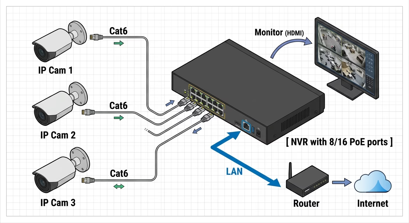
Plug and play: the NVR powers the cameras and gives them IP addresses automatically.
5.2 Medium and large systems: external PoE switches
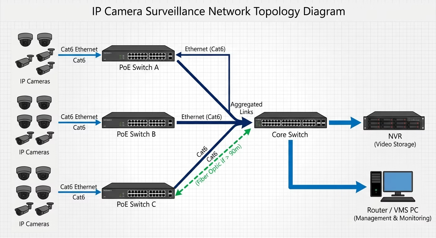
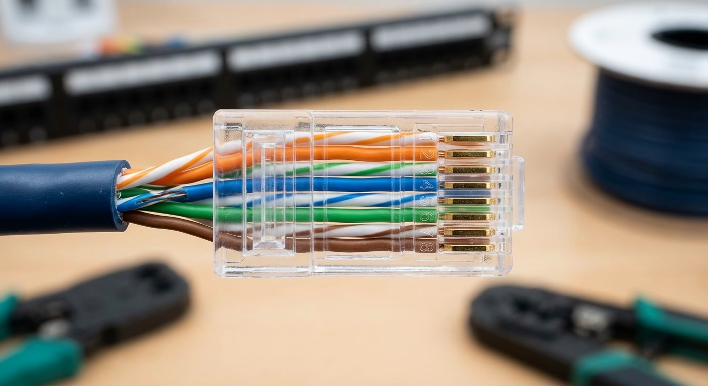
5.3 RJ45 termination: T568B (use the same standard on both ends)
Tips from site:
-
Terminate the rack end on a patch panel, never loose RJ45 plugs into the switch.
-
Keep the total channel (patch cord + cable + patch cord) under 100 m. I design for 90 m maximum.
-
Outdoors, use UV-resistant, outdoor-rated Cat6 and a weatherproof junction box behind the camera.
-
Keep Cat6 at least 300 mm away from power cables, or cross at 90 degrees.
-
Test every cable with a cable tester before mounting the camera.
5.4 Example: PoE budget
A 16-port PoE+ switch with a 250 W budget feeds:
-
10 turret cameras at 6 W = 60 W
-
5 bullet cameras with IR at 8 W = 40 W
-
1 PTZ at 25 W = 25 W
Total = 125 W. Add 20 to 25 percent margin for IR at night and winter heaters: about 155 W, well within 250 W. Also check the PTZ port supports 802.3at (30 W).
5.5 Example: bandwidth and storage
Sixteen 4 MP cameras, H.265, 15 fps, medium scene, about 1.8 Mbps each:
-
Total bandwidth = 16 x 1.8 = 29 Mbps
-
Per day = 29 Mbps / 8 x 86,400 s = about 313 GB per day
-
30 days = about 9.4 TB, plus 10 percent headroom = about 10.3 TB
-
Recommendation: 2 x 6 TB surveillance drives (or 2 x 8 TB for growth).
Part 6: DIY Installation Step by Step
Tools: drill with masonry bits, cable tester, RJ45 crimper and punch-down tool, BNC crimper (analog), ladder, cable ties, conduit and fittings, silicone sealant, labeller, laptop, small monitor.
-
Mark positions on walls and ceilings. Mount around 2.5 to 3.5 m high: high enough to avoid tampering, low enough to see faces.
-
Run conduit or trunking from each camera to the rack. Outdoors, use UV-rated PVC or GI conduit.
-
Pull cables with a draw wire. Leave 1 m spare at the camera and 3 m at the rack.
-
Label both ends immediately (for example CAM-01).
-
Terminate: keystone or RJ45 at the camera, patch panel at the rack (IP); BNC and DC plug (analog).
-
Test every cable with a tester. Fix faults now, not after the ceiling is closed.
-
Mount the cameras. Use a junction box outdoors, and seal every cable entry with silicone and a drip loop.
-
Connect the rack: patch panel to switch, switch to NVR, NVR to UPS.
-
Power up and check each camera appears on the NVR.
-
Configure the NVR: set time and date (NTP), activate cameras with strong passwords, set recording schedule, stream settings (H.265, 15 fps, sensible bitrate), and motion or AI detection.
-
Aim and focus each camera at night and day. Avoid pointing directly into the sun or a bright light.
-
Set up remote viewing through the manufacturer’s app. Change the default ports and passwords, and update firmware.
-
Document everything: camera list, IP addresses, passwords (in a secure place), and a simple as-built drawing.
Part 7: Testing and Troubleshooting
|
Problem |
Likely cause |
Fix |
|
No video (analog) |
Bad BNC crimp, wrong format (TVI vs CVI) |
Re-terminate, set the DVR channel to the correct format |
|
Rolling lines or noise |
Ground loop, CCA cable, near power cables |
Use pure copper, ground loop isolator, re-route |
|
Picture fine by day, black or rebooting at night |
Voltage drop or PoE budget exceeded when IR turns on |
Thicker cable, local PSU, check switch budget |
|
IP camera not detected |
Different subnet, bad cable, IP conflict |
Use the brand’s search tool (SADP, ConfigTool), test cable |
|
Camera keeps dropping |
Cable over 100 m, bad termination, faulty port |
Shorten run, re-terminate, move port |
|
White glare at night |
IR reflecting off dome bubble or nearby wall |
Clean dome, reposition, use turret type |
|
Recording gaps |
Hard drive failing, bandwidth over NVR limit |
Check HDD health, lower bitrate, larger NVR |
|
Face is dark at the door |
Strong backlight |
Enable WDR, reposition camera |
Part 8: Advanced Topics for Engineers
8.1 Network design
-
Separate camera traffic with a dedicated camera VLAN (for example VLAN 10) and a management VLAN for switches and NVRs.
-
Use managed PoE switches with SFP uplinks. Connect field switches to the core over fiber when the distance is above 90 m.
-
Size uplinks: a 16-camera switch at 2 Mbps per camera needs about 32 Mbps. A 1 Gbps uplink is plenty, but go 10 Gbps at the core for 200+ cameras or AI servers.
-
Enable IGMP snooping if you use multicast for multiple viewing stations.
8.2 Cybersecurity
-
Change every default password, use unique strong passwords.
-
Disable P2P cloud on high-security sites and use VPN for remote access.
-
Disable UPnP on the router. Never port-forward the NVR directly to the internet.
-
Keep firmware updated and disable unused services (Telnet, SSH, FTP).
-
Put cameras on an isolated VLAN with no internet access.
8.3 Redundancy
-
RAID 5 or 6 on the NVR for critical sites.
-
UPS sized for at least 30 minutes, with surge protection on outdoor cable runs.
-
For large sites, consider a VMS (Milestone, Genetec, or similar) with failover recording.
8.4 Integration
-
Integrate with access control (door events with video), fire alarm (cameras call up on alarm), and intrusion systems.
-
Use ONVIF Profile S and T for multi-brand compatibility, and test it before buying in bulk.
Part 9: DIY Project, a 60-Camera IP CCTV System
9.1 The site
A typical warehouse with a two-storey office block in an industrial area:
-
Warehouse: 80 m x 50 m, 10 m high ceiling, 4 loading bays.
-
Office block: ground floor (reception, offices) and first floor (offices, meeting room).
-
External: perimeter fence, main gate, staff parking, truck yard.
-
Main rack (MDF) in the office server room; one field rack (IDF) inside the warehouse, about 120 m away.
9.2 Camera schedule
|
Zone |
Qty |
Camera |
Lens |
Purpose |
|
Office ground floor (reception, corridors, entrances) |
10 |
4 MP turret, WDR |
2.8 mm |
Recognise faces at doors |
|
Office first floor |
8 |
4 MP turret |
2.8 mm |
General overview |
|
Server room and stores |
2 |
4 MP turret |
2.8 mm |
Asset protection |
|
Warehouse aisles and racks |
16 |
4 MP bullet / turret |
4 mm or 6 mm |
Observe aisles |
|
Loading bays (inside and outside) |
8 |
4 MP bullet, IR 50 m |
2.8 to 12 mm varifocal |
Observe loading |
|
Perimeter fence and truck yard |
10 |
4 MP bullet, IR 60 m |
6 mm or varifocal |
Detect intruders |
|
Parking |
2 |
8 MP bullet |
4 mm |
Overview |
|
Main gate (vehicles) |
2 |
8 MP / LPR |
8 to 32 mm varifocal |
Number plates |
|
Main gate (people) |
2 |
4 MP turret, WDR |
2.8 mm |
Identify at the gate |
|
Total |
60 |
Naming: CAM-[Building]-[Floor]-[Number], for example CAM-OF-GF-01 (Office, Ground Floor), CAM-WH-01 (Warehouse), CAM-EX-01 (External).
9.3 Network topology
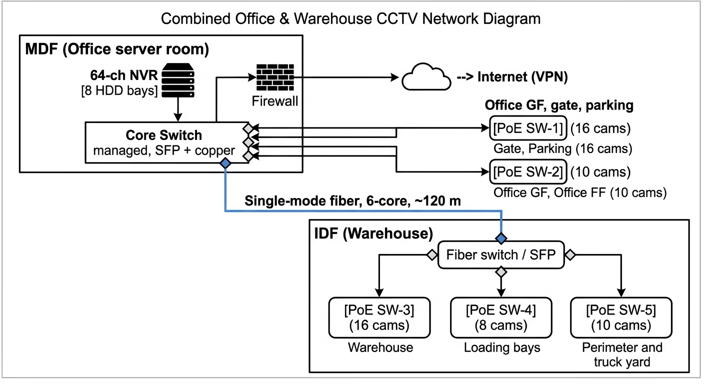
*Long perimeter runs above 90 m use small outdoor PoE switches or media converters in weatherproof boxes, fed by fiber or a local power point.
9.4 Bandwidth and storage calculation
-
56 x 4 MP at H.265, 15 fps, about 1.8 Mbps each = 103 Mbps
-
4 x 8 MP at H.265, 15 fps, about 4.9 Mbps each = 20 Mbps
-
Total recording bandwidth: about 123 Mbps (well under a 320 Mbps NVR limit)
-
Per day: 123 Mbps / 8 x 86,400 s = about 1.33 TB per day
-
30 days retention: about 40 TB, plus 10 percent headroom = about 44 TB
-
Recommended: 8 x 8 TB surveillance drives in RAID 5 = about 51 TB usable.
9.5 PoE budget per switch
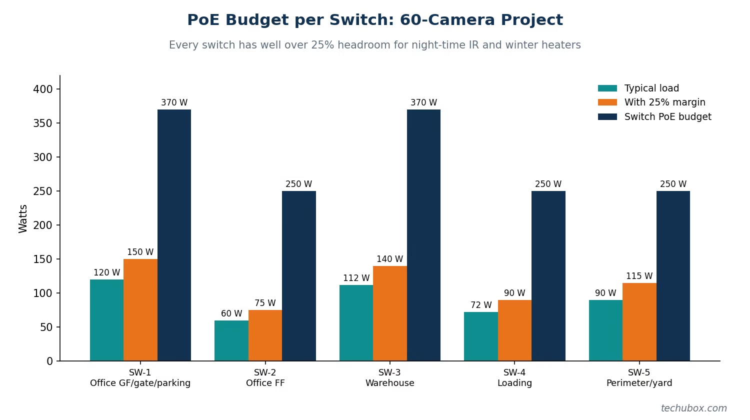
|
Switch |
Cameras |
Typical load |
With 25 percent margin |
Switch to buy |
|
SW-1 Office GF, gate, parking |
16 (10 office, 2 gate turrets, 2 LPR, 2 parking) |
10 x 6 W + 6 x 10 W = 120 W |
150 W |
24-port PoE+, 370 W |
|
SW-2 Office FF and server room |
10 |
10 x 6 W = 60 W |
75 W |
16-port PoE+, 250 W |
|
SW-3 Warehouse |
16 |
16 x 7 W = 112 W |
140 W |
24-port PoE+, 370 W |
|
SW-4 Loading |
8 |
8 x 9 W = 72 W |
90 W |
16-port PoE+, 250 W |
|
SW-5 Perimeter and yard |
10 |
10 x 9 W = 90 W |
115 W |
16-port PoE+, 250 W |
Choose 24-port switches where you want spare ports: leave about 20 percent of ports free for future cameras.
9.6 Bill of materials
|
Item |
Qty |
|
4 MP turret cameras (2.8 mm, WDR) |
24 |
|
4 MP bullet / turret cameras (4 or 6 mm) |
16 |
|
4 MP varifocal bullet cameras (IR 50 to 60 m) |
16 |
|
8 MP bullet cameras (4 mm) |
2 |
|
8 MP LPR / varifocal cameras |
2 |
|
64-channel NVR, 8 HDD bays, 320 Mbps+ incoming |
1 |
|
8 TB surveillance hard drives |
8 |
|
Managed core switch with SFP ports |
1 |
|
Managed PoE+ switches (24-port and 16-port) |
5 |
|
Outdoor PoE switches or media converters in IP66 boxes |
as needed |
|
SFP modules, single-mode (LX) |
6 |
|
6-core single-mode fiber, armoured, with patch panels and pigtails |
about 150 m |
|
Cat6 cable, outdoor-rated for external runs (305 m boxes) |
about 10 boxes (about 3,000 m) |
|
24-port Cat6 patch panels |
4 |
|
Patch cords (0.5 m and 1 m) |
70 |
|
Junction boxes for cameras |
60 |
|
42U rack (MDF) and 12U wall rack (IDF) |
1 each |
|
Online UPS, 3 kVA (MDF), 1.5 kVA (IDF) |
1 each |
|
Surge protectors for outdoor Ethernet runs |
20 |
|
Monitor (32 inch or larger) and mouse |
1 |
|
Conduit, fittings, trunking, cable ties, labels |
as needed |
Cable estimate: 60 cameras x average 45 m = 2,700 m, plus 10 percent waste = about 3,000 m.
9.7 IP address plan
|
Device |
VLAN |
IP range |
|
Cameras |
10 (CCTV) |
192.168.10.101 to 192.168.10.160 |
|
NVR |
10 (CCTV) |
192.168.10.10 |
|
Switches (management) |
99 (MGMT) |
192.168.99.2 to 192.168.99.7 |
|
Viewing PC / VMS client |
10 (CCTV) |
192.168.10.20 to 192.168.10.30 |
|
Gateway / firewall |
10 and 99 |
192.168.10.1 and 192.168.99.1 |
Make the last part of each camera’s IP match its number: CAM-WH-05 = 192.168.10.105. Your maintenance team will thank you.
9.8 Rack layout (MDF, 42U)
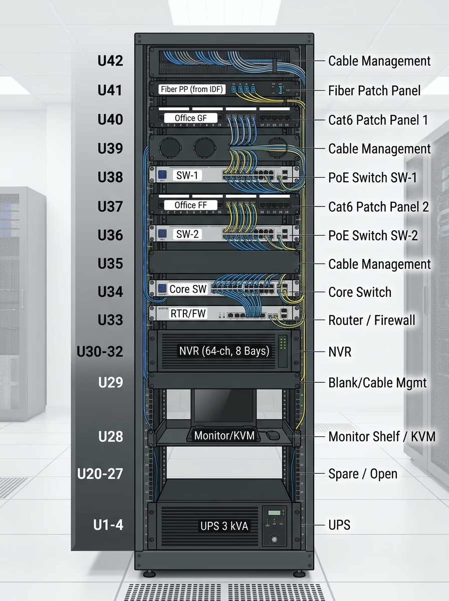
9.9 Installation timeline for a DIY team of 2 to 3 people
|
Week |
Work |
|
1 |
Site survey, final drawings, order materials |
|
2 to 3 |
Conduit and trunking, cable pulling, fiber between MDF and IDF |
|
4 |
Termination, labelling, cable testing; rack installation |
|
5 |
Camera mounting, outdoor junction boxes and sealing |
|
6 |
Switch and NVR configuration, VLANs, camera activation |
|
7 |
Aiming and focus (day and night), recording schedules, analytics |
|
8 |
9.10 Commissioning checklist
-
☐ Every cable tested and labelled at both ends
-
☐ All 60 cameras online with correct names and IP addresses
-
☐ Time synced via NTP on NVR, switches and cameras
-
☐ Recording verified on every channel (play back yesterday’s footage)
-
☐ Retention checked against the 30-day target after one week
-
☐ Night image checked on every outdoor camera
-
☐ Gate cameras reading plates and faces clearly
-
☐ RAID healthy, HDD alerts enabled
-
☐ UPS tested by switching off mains
-
☐ Default passwords changed, firmware updated, P2P disabled where required
-
☐ Remote access working through VPN or approved app
-
☐ As-built drawing, camera list and IP schedule handed over
Frequently Asked Questions
-
Is HD analog or IP better for a new CCTV installation?
For any new build, especially above 16 cameras, IP is the better choice. It scales more easily, supports AI analytics, licence plate recognition and higher resolutions, and needs only one Cat6 cable per camera with PoE. HD analog (HD-TVI, HD-CVI, AHD) remains a cheap, solid upgrade where good coax is already installed. - What is the maximum cable distance for an IP camera?
A copper Cat6 run is limited to 100 m including patch cords. In practice, design for 90 m maximum. For longer distances use fiber with an SFP uplink, or a small outdoor PoE switch or media converter near the camera. - How much storage do I need for 60 IP cameras?
For 56 x 4 MP and 4 x 8 MP cameras at H.265, 15 fps, the total recording bandwidth is about 123 Mbps, which is roughly 1.33 TB per day. For 30 days of retention, plan for about 44 TB including 10 percent headroom, for example 8 x 8 TB surveillance drives in RAID 5. - What is a PoE budget and why does it matter?
The PoE budget is the total wattage a switch can supply to all ports together. Add up the real camera loads, then add 20 to 25 percent for infrared at night and heaters in winter. If the budget is exceeded, cameras reboot or go black when the IR turns on. - Do CCTV cameras need their own VLAN?
On any business or multi-camera site, yes. A dedicated camera VLAN plus a separate management VLAN keeps video traffic away from office traffic, limits the damage if a camera is compromised, and makes it easy to block internet access for cameras.
Final Tips from the Field
-
Spend on cable and termination quality. A cheap camera on good cable beats an expensive camera on bad cable.
-
Design for night first. Most incidents happen at night, and most bad installations fail at night.
-
Leave spare capacity: 20 percent spare switch ports, NVR channels and PoE budget.
-
Label and document everything. It saves days during maintenance.
-
Check local regulations for your facility type before you design, including retention period and approved equipment.
Have a question about your own installation? Leave a comment below or use the Work With Me form, and I will help you plan it.