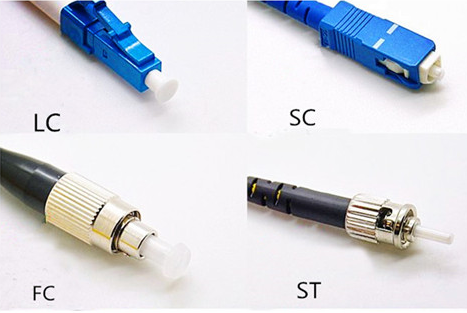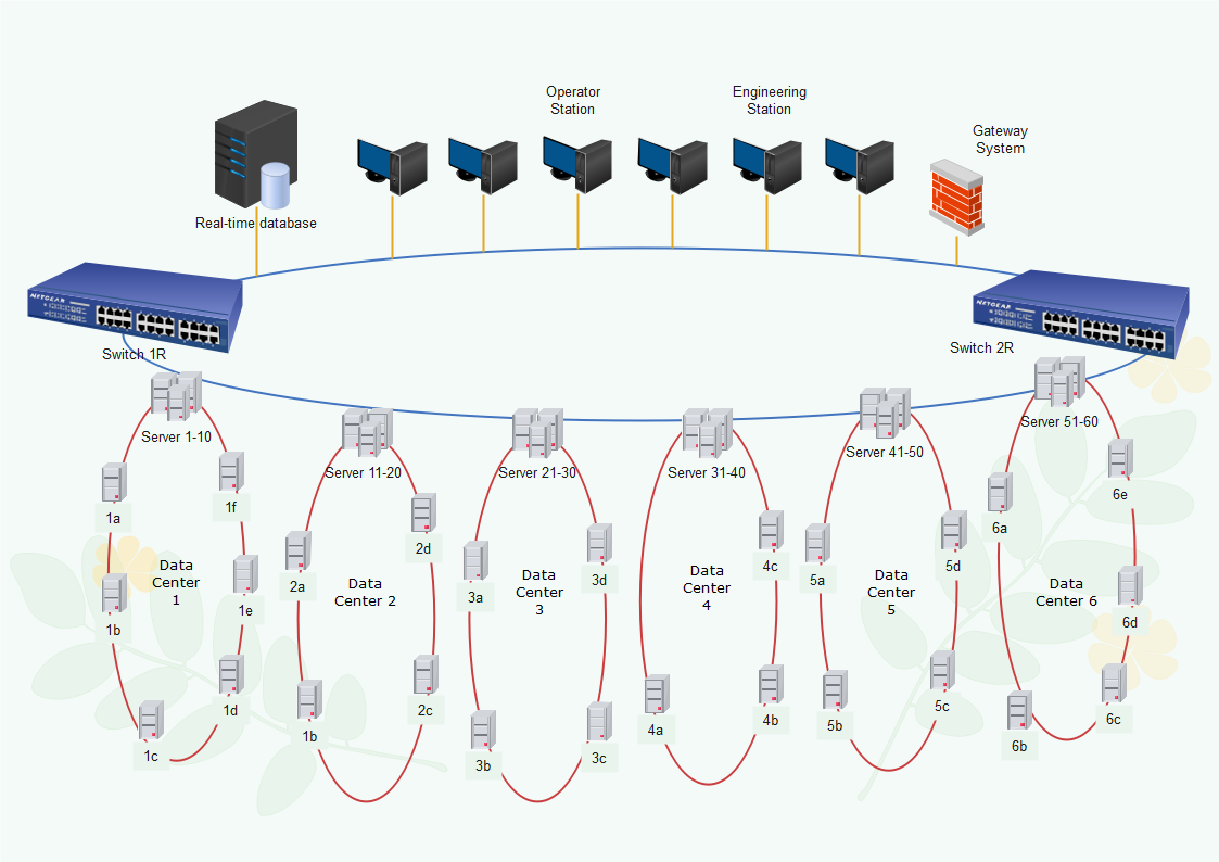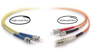
1000BaseX
A type of Gigabit Ethernet technology that uses fibre optic cables to transfer data at a rate of 1 gigabit per second mainly over fiber optic & sometimes over copper-shielded cable.
The data transfer range of 1000BASE-X starts at 25 meters to 70 km with a single-mode fibre channel.
There are two main variants of 1000BaseX:
• 1000BASE-SX
• 1000BASE-LX
1000Base-SX.
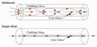
1000BASE-SX is a Gigabit Ethernet standard for optical fiber cabling. “SX” stands for “short wavelength, 850 nanometers”, which refers to the wavelength of the light used to transmit data & supports a maximum transmission distance of 550 meters over multimode fiber optic cable with a core diameter of 50 or 62.5 micrometers.
1000BASE-SX is commonly used in local area networks (LANs) to provide high-speed data transfer between switches, routers, and servers. It is also used in data centers and other enterprise environments
1000Base-SX uses multi-mode fibre optic cabling and has a maximum range of 550 meters.
1000BASE-LX
1000Base-LX Gigabit Ethernet standard for optical fiber cabling. The “LX” stands for “long wavelength, 1310 nanometers”, which refers to the wavelength of the light used to transmit data over the fiber cable.
This standard supports a maximum transmission distance of 10 kilometers over single-mode fiber optic cable.
1000BASE-LX is commonly used to connect network switches and routers over longer distances, such as between buildings on a campus or in a metropolitan area network (MAN)
What does it means…
- SFP modules
- Media Converter
-
SFP modules
SFP stands for Small Form-factor Pluggable transceiver module used in networking equipment to convert electrical signals into optical signals and vice versa. SFP modules are designed to be hot-swappable.
SFP modules are commonly used in Ethernet switches, routers, and other networking equipment to provide connectivity over optical fiber or copper cabling. They come in a variety of types:
SFP, SFP+, and SFP28,
support different data rates and transmission distances.
SFP modules are also available in different configurations, including single-mode and multimode fiber optic, and copper twisted-pair.
A Fibre media converter is a networking device used to convert the transmission media of a network from one format to another. such as a copper-based Ethernet network to a fibre optic or Fiber optic to copper network.
Media converters typically have two ports, one for the source network other for the destination network. They convert the electrical signals or Optical signals from one type of media to another, allowing the two networks to communicate with each other.
Media converters can support a variety of transmission media:
copper twisted-pair
fibre optic
and wireless. They can also support different data rates and transmission distances, depending on the selected models.

More Fiber Optic Terms You Will Meet on Site
On real projects, drawings, BOQs and test reports use many more terms than those above. The table below explains the most common ones in ELV, CCTV and LAN work. Values shown are typical; confirm against datasheets and the project specification.
| Term | What it means | Typical value or note |
|---|---|---|
| OS2 | Single-mode fiber category (9/125 µm), normally to ITU-T G.652.D low water peak. The usual choice for backbones and long CCTV runs. | Typically about 0.35 dB/km at 1310 nm and 0.25 dB/km at 1550 nm (cabled fiber is often specified at 0.4 dB/km maximum). |
| OM3 | Laser-optimised 50/125 µm multimode fiber, usually with an aqua jacket. | 10GBASE-SR is rated to about 300 m. |
| OM4 | Higher-bandwidth 50/125 µm multimode fiber, aqua or violet (Erika violet) jacket depending on the market. | 10GBASE-SR is rated to about 400 m. |
| OM5 | Wideband multimode fiber carrying several wavelengths (about 850 to 950 nm). Lime green jacket. | Same reach as OM4 at 850 nm; the benefit only appears with SWDM optics. |
| Wavelength (nm) | The wavelength of light the transceiver uses. | Multimode: 850 nm (and 1300 nm). Single-mode: 1310 nm and 1550 nm. |
| Attenuation (dB/km) | Loss of light inside the fiber itself, per kilometre of length. | Multimode is typically about 3 dB/km at 850 nm; single-mode well under 0.5 dB/km. |
| Insertion loss | Total light lost when a component (connector pair, splice, adapter, whole link) is placed in the path. Lower is better. | About 0.3 dB per mated connector pair is a common typical figure; TIA-568 allows up to 0.75 dB. |
| Return loss | How much light is reflected back toward the source at a connection. A higher number in dB is better. | UPC typically 50 dB or better; APC typically 60 dB or better. |
| UPC | Ultra Physical Contact polish: a flat, domed end face. Single-mode UPC connectors are usually blue. | Standard for Ethernet links and most SFP connections. |
| APC | Angled Physical Contact polish: the end face is cut at 8 degrees so reflections leave the core. Connector body is green. | Common in GPON/FTTH and RF-over-fiber video. Never mate with UPC. |
| Splice loss | Loss at a permanent joint between two fibers. | Fusion splice typically 0.1 dB or less; mechanical splice usually higher, around 0.3 to 0.5 dB. |
| Pigtail | A short fiber with a factory connector on one end; the bare end is fusion-spliced to the cable. | Usually 1 to 2 m, tight-buffered, colour-coded to match the cable cores. |
| Patch panel / ODF | Optical Distribution Frame: the rack-mounted box where cable cores are spliced to pigtails and presented on adapters for patching. | Sized by port count (12, 24, 48, 96) and adapter type (LC duplex, SC simplex). |
| OTDR | Optical Time Domain Reflectometer. It plots loss against distance, showing each splice, connector, bend and break. | Used for acceptance testing and fault finding. Test from both ends for accurate splice values. |
| SFP+ | The 10 Gbps version of the SFP module, same physical size. | 10GBASE-SR (850 nm, multimode) and 10GBASE-LR (1310 nm, single-mode, about 10 km) are the common types. |
| BiDi SFP | Sends and receives on one fiber using two wavelengths. | Used as a matched pair (1310/1550 nm at one end, 1550/1310 nm at the other). |
How These Terms Fit Together in a Real Link
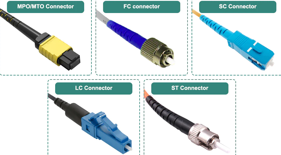
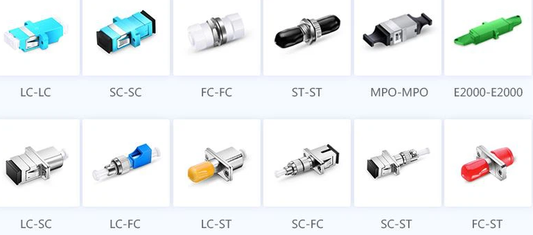
In a typical CCTV backbone, an SFP in the core switch connects by LC patch cord to the ODF, where a pigtail is fusion-spliced to one core of the OS2 cable. The far end mirrors this to reach the edge switch.
Each item adds insertion loss: the fiber adds attenuation per kilometre, and every splice and connector pair adds its own loss. Add them up and compare the total with the SFP power budget to confirm a safe margin.
Choosing between single-mode and multimode
- Inside one building, under about 300 m, OM3 or OM4 with 850 nm optics works well.
- For campus, perimeter CCTV and anything that may grow later, OS2 single-mode is usually the safer choice.
- Do not mix fiber types in one link. A multimode patch cord on a single-mode link, or OM1 (62.5 µm) joined to OM3 (50 µm), causes high loss.
FAQ
What is the difference between APC and UPC connectors?
Both are polish types for the connector end face. UPC is flat-domed and usually blue; APC is angled at 8 degrees and green. APC reflects less light back to the source, which matters for GPON and analogue video. Never mate the two: it causes high loss and can damage the end faces.
Is OS1 the same as OS2?
Both are 9/125 µm single-mode fiber. OS1 is generally associated with tight-buffered indoor cable and OS2 with lower-attenuation, low water peak cable. Most new specifications call for OS2.
Can I use a 1310 nm SFP on multimode fiber?
As a rule, no. Use 850 nm optics on multimode fiber and 1310/1550 nm optics on single-mode fiber. Mode-conditioning patch cords for legacy cases are the exception.
Why test with an OTDR if a power meter already shows the total loss?
A power meter shows whether the whole link passes. An OTDR shows where each loss happens and how far along the cable, so it is the right tool for checking splices and locating breaks.
Related tools
Planning a fiber backbone for a CCTV or LAN project? Use our free Network & CCTV Designer to lay out switches, fiber links and cameras before you build the BOQ.