
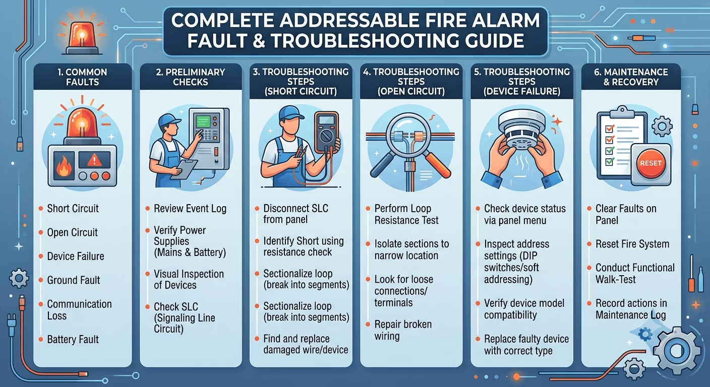
Complete Addressable Fire Alarm Fault & Troubleshooting Guide
Complete Fault & Troubleshooting Guide and Fix
This guide covers every fault category an engineer will encounter on an analogue addressable fire alarm panel — not just the loop-level faults, but power, battery, network, module, and device-health faults as well. It is written specifically for addressable systems (Notifier, Edwards, Siemens, Hochiki ESP, Apollo XP95/Discovery, Bosch, and similar platforms), since addressable panels report faults at a much finer resolution than conventional panels . Each fault entry includes what it means, a step-by-step diagnostic path — followed by a full addressable commissioning procedure from pre-energization testing through formal handover
1. How an Addressable Loop Works — Why Faults Report the Way They Do
An analogue addressable loop is wired out from the panel’s loop card, through every device, and back to the same card — a closed ring, not a dead-end radial circuit. This lets the loop card drive the circuit from both directions simultaneously, so a single break does not take the whole loop down. Every detector, call point, sounder base, and I/O module carries a unique digital address, which is how the panel can report faults, alarms, and isolations down to the individual device rather than just a zone.
Because of this architecture, addressable panels can report a far wider range of fault conditions than conventional panels — not just loop wiring faults, but device health (contamination/drift), module-level faults, isolator activity, power and battery health, and network communication between panels and repeaters.
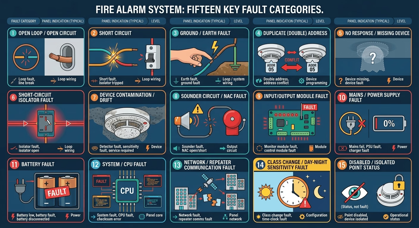
2. Complete Addressable Fault Index
Every addressable panel fault falls into one of the categories below.
| # | Fault Category | Panel Indication (typical) | Level |
| 1 | Open Loop / Open Circuit | Loop fault, line break, open circuit | Loop wiring |
| 2 | Short Circuit | Short fault, isolator tripped | Loop wiring |
| 3 | Ground / Earth Fault | Earth fault, ground fault | Loop / system wiring |
| 4 | Duplicate (Double) Address | Double address, address conflict | Device programming |
| 5 | No Response / Missing Device | Device missing, device fault | Device |
| 6 | Short-Circuit Isolator Fault | Isolator fault, isolator open | Loop wiring |
| 7 | Device Contamination / Drift | Detector fault, sensitivity fault, service required | Device |
| 8 | Sounder Circuit / NAC Fault | Sounder fault, NAC open/short | Output circuit |
| 9 | Input/Output Module Fault | Monitor module fault, control module fault | Module |
| 10 | Mains / Power Supply Fault | Mains fail, PSU fault, charger fault | Power |
| 11 | Battery Fault | Battery low, battery fault, battery disconnected | Power |
| 12 | System / CPU Fault | System fault, CPU fault, checksum error | Panel core |
| 13 | Network / Repeater Communication Fault | Network fault, repeater comms fault | Panel network |
| 14 | Class Change / Day-Night Sensitivity Fault | Class change fault, time-clock fault | Configuration |
| 15 | Disabled / Isolated Point Status | Point disabled, device isolated (status, not fault) | Operational status |
3. Open Loop (Open Circuit) Fault
An open loop means the continuous electrical path of the loop has been broken. Because the loop card drives from both ends, devices on either side of the break usually stay online — the panel identifies the break by the last device it can still poll from each direction.
Common Causes
- Loose or missing terminal connection at a detector base or module
- Cable damage during ceiling, partition, or fit-out works after handover
- Detector head not fully seated into its base
- Cut, crushed, or rodent-damaged cable
- A bad joint at a junction box or floor distribution point
Troubleshooting Steps
- On the panel, note the loop number and the last responding device address before the break in each direction.
- Refer to the as-built loop wiring diagram to locate the device’s physical position.
- Disconnect the loop from the panel card and test continuity/resistance across the two loop cores with a multimeter.
- Bisect the loop at an accessible junction or floor distribution board and test each half separately to narrow down the faulty section.
- Inspect suspect device bases for loose screw terminals, reversed polarity, or a head not clicked fully into its base.
- Rectify (re-terminate, replace cable, reseat device) and re-energize.
- Confirm the loop reads normal on the panel with zero faults.
| Commissioning Tip
• Always test loop continuity before connecting to the loop driver card — an open loop can appear ‘normal’ if devices near the panel still respond, masking a downstream break until it’s too late. |
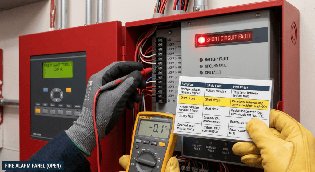
4. Short Circuit Fault
A short occurs when the two loop conductors make unintended contact, collapsing the voltage the loop card sees. On addressable loops fitted with short-circuit isolators, the isolators either side of the fault open automatically, so the fault report points directly to the affected isolator segment.
Common Causes
- Stripped cable insulation touching between conductors inside a back box
- Positive and negative cores crossed at termination
- Water ingress at an external call point or beam detector enclosure
- Cable pinched under conduit clamps, trunking lids, or ceiling grid
Troubleshooting Steps
- Note which isolator segment or loop section the panel flags — this narrows the search immediately.
- Isolate the loop and measure resistance between the two cores at the panel; a reading near zero ohms confirms a hard short.
- Walk the affected section and inspect back boxes and junction boxes for pinched or stripped cores, especially around recent works.
- Disconnect suspect segments progressively, working outward from the isolators, re-measuring after each to locate the shorted section.
- Re-terminate correctly, replace damaged cable, and seal any enclosure exposed to moisture.
- Re-energize and confirm the isolators reset and the loop reports normal.
5. Ground (Earth) Fault
A ground fault means a loop or system conductor has made contact with earth potential — commonly the metal conduit, trunking, or building steel. A single earth fault can mask a second, unrelated fault by effectively creating an unintended short, so panels flag it even though it may not stop the loop from functioning immediately.
Common Causes
- Cable insulation damaged at a conduit edge or gland
- Moisture ingress in an external device causing conductor-to-earth leakage
- A conductor accidentally landed on an earth terminal inside a junction box
Troubleshooting Steps
- Disconnect the field wiring from the panel’s loop terminals and the earth bar.
- Measure insulation resistance between each conductor and earth using an insulation tester (megger) at 250V DC — healthy cable should read several hundred megohms; a fault reads near zero.
- Segment the circuit at accessible junction boxes and re-test each segment to isolate the faulty run.
- Inspect the isolated section for damaged insulation, pinched cable, or a core touching a metal gland or tray.
- Repair or replace the affected cable run and confirm insulation resistance meets the panel manufacturer’s minimum threshold (commonly >20 MΩ) before reconnecting.
| Safety Reminder
• A standard multimeter continuity check will not reliably reveal a high-resistance earth leakage path that later develops into a full fault under humidity or heat — always use a proper insulation resistance tester on fire alarm cabling. |
6. Duplicate (Double) Address Fault
Every device on an addressable loop carries a unique software address. If two devices share the same address — almost always a programming error — the panel cannot reliably distinguish between them and raises a duplicate/double address fault, often with erratic or ‘ghost’ readings from that address.
Common Causes
- Two devices set to the same address using a handheld addressing tool or DIP switches during installation
- A replacement device fitted after handover without checking the address of the unit it replaced
- Copy-paste or range errors when using auto-addressing software during bulk commissioning
Troubleshooting Steps
- On the panel or loop mapping software, identify the address number reported as duplicated.
- Cross-reference the as-built device address schedule against physical device labels to identify both devices sharing the address.
- Use a handheld addressing tool’s ‘walk test’ or ‘locate’ function — it makes the correct device respond (LED flash) when queried, helping you tell the two apart.
- Re-address one of the two devices to its correct, unique address using the manufacturer’s tool (magnetic wand, rotary switch, or software auto-addressing).
- Update the as-built address schedule immediately to prevent recurrence.
- Run an auto-learn / loop scan from the panel to confirm every device now reports a unique address.
7. No Response / Missing Device Fault
This occurs when the panel expects a device at an address (from the last auto-learn) but gets no response — distinct from an open loop, since the rest of the loop may be perfectly healthy.
Common Causes
- Device physically removed or not yet installed at that point
- Head lifted or removed for ceiling/fit-out works and not replaced
- Device left in isolate/disabled mode from previous testing
- Wrong device type fitted to the base (mismatched head and base do not communicate)
- Damaged or dry joint at that specific device’s terminals
Troubleshooting Steps
- Confirm the device is physically present and its base is fully engaged.
- Check whether the device was left disabled/isolated from earlier testing or maintenance.
- Verify the correct device type is fitted to the base for that address.
- Inspect the device’s terminals for a damaged or dry joint.
- Swap in a known-good spare of the same type to confirm whether the original device itself has failed.
8. Short-Circuit Isolator Fault
Isolator modules sit at intervals along the loop (or are built into device bases) and automatically disconnect a section when they detect a short, protecting the rest of the loop. An isolator fault means an isolator has opened, or has failed to reset after the short has been cleared.
Common Causes
- A short circuit downstream of the isolator that has not yet been physically cleared
- Isolator module itself has failed
- Loop scan run before the isolator had time to reset after the short was cleared
Troubleshooting Steps
- Confirm the underlying short circuit (Section 4) has actually been cleared before expecting the isolator to reset.
- Power-cycle the loop or run a manual isolator reset from the panel where supported.
- If the isolator does not reset after the short is confirmed cleared, test the isolator module itself and replace if faulty.
- Re-run the loop scan and confirm the segment returns to normal.
9. Device Contamination / Drift Fault (Detector Health)
Analogue addressable detectors report their sensor chamber value to the panel continuously, which allows the panel to flag a detector whose reading has drifted outside its normal window — usually due to dust or contamination in the smoke chamber — before it either fails to detect smoke correctly or starts causing nuisance alarms.
Common Causes
- Dust and construction debris accumulated in the smoke chamber (very common during and shortly after fit-out works)
- Detector left uncapped during dusty works instead of using a dust cap or bag
- Detector approaching end of service life or requiring scheduled cleaning
- Insects or debris inside the chamber in externally exposed detectors
Troubleshooting Steps
- Identify the flagged device address from the panel’s maintenance/fault log.
- Check the device’s analogue value against the manufacturer’s normal range using the panel or loop software.
- Physically inspect and clean the detector using the manufacturer’s approved cleaning procedure (compressed air or dedicated detector cleaning tool) — do not use water or solvents.
- If cleaning does not bring the reading back within range, replace the detector head.
- Log the cleaning/replacement in the maintenance record — recurring contamination on the same device usually points to a local dust source that needs addressing at the works level, not just the detector.
10. Sounder Circuit / NAC (Notification Appliance Circuit) Fault
This covers faults on conventional sounder circuits driven from the panel or from addressable sounder bases/control modules, reported as an open circuit, short circuit, or ground fault on the notification output rather than the detection loop.
Common Causes
- Open circuit: disconnected sounder, missing EOL resistor on a conventional NAC, cable break
- Short circuit: damaged cable insulation or incorrect polarity at a sounder base
- Sounder base fitted without the sounder head, or wrong sounder type for the circuit
- Overloaded circuit — too many sounders drawing more current than the circuit or power supply is rated for
Troubleshooting Steps
- Identify the specific NAC/sounder circuit or addressable sounder base address flagged.
- Test the circuit for continuity (open) or near-zero resistance (short) at the panel/module terminals.
- Walk the circuit checking each sounder base for correct termination, presence of the sounder head, and EOL resistor where applicable.
- Calculate total connected sounder current draw against the circuit/power supply rating if the fault appears only when multiple sounders activate together.
- Rectify wiring or replace the faulty sounder/base and re-test by triggering an evacuation test.
11. Input / Output Module Fault
Monitor modules (inputs from other systems) and control modules (outputs to dampers, door holders, AHU shutdown, lift recall, etc.) can report faults independently of the detection devices on the same loop.
Common Causes
- Wiring fault on the monitored input or controlled output side of the module (separate from the loop wiring)
- Module not configured correctly in the panel’s cause-and-effect programming
- Interfaced equipment (damper actuator, door holder, relay) failed or disconnected
- Power supply to the module or interfaced device lost
Troubleshooting Steps
- Identify the module address and whether the fault is on the loop side or the field wiring side of the module.
- Check field wiring continuity to the interfaced device (damper, door holder, relay, etc.).
- Verify the module’s cause-and-effect programming still matches the current cause-and-effect matrix — a fault can also appear as an unexpected non-response during testing if programming has drifted from the as-built matrix.
- Confirm power supply to the interfaced equipment.
- Re-test the specific cause-and-effect line involving that module after rectification.
12. Mains / Power Supply Fault
The panel continuously monitors its incoming mains supply and internal power supply unit (PSU)/charger. This fault group covers mains failure and PSU/charger faults, separate from the battery itself.
Common Causes
- Loss of incoming mains power to the panel
- Tripped breaker or blown fuse on the panel’s dedicated mains supply
- Faulty charger card unable to maintain correct float/boost charge voltage
- Loose or corroded mains input terminals
Troubleshooting Steps
- Check the panel’s dedicated circuit breaker and confirm mains voltage is present at the panel’s incoming terminals.
- Verify the PSU output voltage against the manufacturer’s specified range using a multimeter at the PSU output terminals.
- Inspect mains input terminals for looseness or corrosion.
- If mains is confirmed present but the panel still reports a PSU fault, test/replace the charger card per manufacturer guidance.
- Confirm the fault clears and the panel returns to mains-normal indication.
13. Battery Fault
Covers low battery voltage, battery disconnected, and failed battery load-test conditions — distinct from a mains/PSU fault, since the panel can run correctly on mains while still flagging a battery problem underneath.
Common Causes
- Batteries reaching end of service life (typically 4–5 years for sealed lead-acid types used in fire panels)
- Loose or corroded battery terminal connections
- Battery fuse blown
- Undersized battery bank for the connected load (common after sounders/devices are added post-commissioning without re-calculating standby load)
Troubleshooting Steps
- Measure battery voltage under load and compare against the manufacturer’s minimum threshold.
- Inspect battery terminals and the battery fuse for looseness, corrosion, or an open fuse.
- Run the panel’s battery load test function (where available) to confirm the batteries can sustain the required standby and alarm duration.
- Recalculate standby (typically 24 hours) plus alarm (typically 30 minutes) load against installed battery Ah rating if devices/sounders have been added since original commissioning.
- Replace batteries as a matched pair/set — never mix old and new batteries in the same bank.
14. System / CPU Fault
A system or CPU fault (sometimes shown as a checksum or database error) indicates the panel’s own processing or configuration memory has an internal problem, rather than anything in the field wiring.
Common Causes
- Corrupted configuration database after an incomplete programming upload
- Firmware fault or watchdog reset event
- Faulty CPU/main board
- Power interruption during a programming save operation
Troubleshooting Steps
- Note the exact fault code/message shown — manufacturer documentation ties specific codes to specific internal faults.
- Re-upload the panel’s configuration from a verified backup file where the fault is database-related.
- Power-cycle the panel correctly per manufacturer procedure and observe whether the fault clears.
- If the fault persists after a clean configuration reload, escalate to the manufacturer’s technical support or replace the CPU/main board under warranty.
- Always keep a current configuration backup off-panel (on the O&M laptop/USB) specifically to make this recovery fast.
| Commissioning Tip
• Take and store a configuration backup immediately after final commissioning and after every subsequent programming change — this turns a CPU/database fault from a re-programming exercise into a five-minute restore. |
15. Network / Repeater Communication Fault
On multi-panel or networked systems (main panel with repeater panels, or multiple panels networked across a large building), this fault indicates a breakdown in communication between panels rather than a fault on any single loop.
Common Causes
- Break or damage in the network cable (RS485 or manufacturer-specific network bus) between panels
- Incorrect network address or baud rate configuration on one panel/repeater
- Missing or incorrect network termination resistor at the end of the network run
- Power loss at a repeater panel making it drop off the network
Troubleshooting Steps
- Identify which panel/repeater on the network is reporting the communication loss.
- Check network cable continuity between the reporting panel and its nearest neighbor on the network.
- Confirm network address and baud rate settings match across all panels on the network per the design document.
- Verify termination resistors are fitted only at the two physical ends of the network run, not at intermediate panels.
- Confirm power supply status at each repeater panel in the affected section.
16. Class Change / Day-Night Sensitivity Fault
Some addressable panels support time-based sensitivity switching (day/night or occupied/unoccupied class change) for detectors in areas like warehouses or plant rooms. A class change fault means the panel’s internal clock or the scheduled switch itself has failed to execute.
Common Causes
- Panel’s real-time clock has drifted or lost its backup (e.g., after extended power loss with a depleted clock battery)
- Class change schedule not configured or configured incorrectly after a programming update
- Firmware issue affecting the scheduling function
Troubleshooting Steps
- Check and correct the panel’s real-time clock date/time setting.
- Verify the class change schedule programming against the intended day/night sensitivity design.
- If the panel uses a separate clock backup battery/cell, check and replace it if depleted.
- Re-test by observing the sensitivity class actually switches at the scheduled time.
17. Disabled / Isolated Point Status (Not a Fault — But Must Be Checked)
A disabled or isolated device does not raise a fault on most panels — it is a deliberate operational status, typically set during maintenance, hot works, or testing. It is included here because an isolated device provides no fire protection at all, and forgotten isolations are one of the most common findings during fire alarm audits on GCC sites.
Common Causes
- Device isolated for hot works or dusty works and not re-enabled afterward
- Zone/loop disabled during a service visit and left disabled
- Device disabled during commissioning testing and not returned to normal
Checking Procedure
- Run the panel’s ‘disablements’ or ‘isolated points’ report — most addressable panels can list every currently disabled point in one screen.
- Cross-check every listed isolation against an active, time-bound permit-to-work or test record — there should be no isolation without a documented reason and expected re-enable time.
- Re-enable any isolation with no active justification immediately.
- Make a documented disablement log part of the routine service visit checklist, not just the commissioning handover.
| Audit Finding
• On service visits, always start with the disablements report before looking at any other fault — a device left isolated after previous works is silent, has no active fault indication, and is the single highest-risk finding on an otherwise ‘fault-free’ panel. |
18. Quick-Reference Fault Diagnosis Table
| Symptom | Likely Fault | First Check |
| Devices beyond a point unresponsive, break indicated | Open loop | Loop continuity test at panel terminals |
| Voltage collapse, isolators tripped | Short circuit | Resistance between loop cores (should not read ~0Ω) |
| Earth fault LED lit, no other symptom | Ground fault | Insulation resistance test to earth (megger) |
| Two devices behave identically / flicker together | Duplicate address | Cross-check as-built address schedule |
| Single device missing after auto-learn | No response / missing device | Physical inspection of device and base |
| Isolator indication after a cleared short | Isolator fault | Confirm short is cleared, then reset/power-cycle |
| Detector reading drifting or nuisance alarms | Contamination / drift | Check analogue value vs. normal range, clean chamber |
| Sounders silent or partial on evacuation test | Sounder/NAC fault | Continuity/short test on notification circuit |
| Damper/door holder not responding on test | I/O module fault | Check field wiring and cause-and-effect programming |
| Panel on battery unexpectedly | Mains/PSU fault | Check breaker and PSU output voltage |
| Panel functions but flags battery issue | Battery fault | Load-test battery voltage, check terminals/fuse |
| Repeated unexplained resets or checksum error | System/CPU fault | Reload verified configuration backup |
| Repeater panel not mirroring main panel | Network/repeater fault | Check network cable, address, termination |
| Sensitivity not switching at scheduled time | Class change fault | Check panel clock and schedule programming |
| No alarm on activation despite panel showing normal | Disabled/isolated point | Run disablements report, cross-check permits |
19. Full Addressable Fire Alarm Commissioning Procedure
Systematic commissioning catches nearly every fault above before a system is ever presented for client witness testing or civil defense inspection. This sequence reflects the process used across FireNor addressable commissioning projects in the GCC, from site readiness through formal handover.
Stage 1 — Pre-Commissioning Site Readiness
- Confirm all first-fix and second-fix cabling is complete and labeled per the as-built drawings.
- Verify the panel, repeater panels, and power supply units are permanently powered and earthed to the building earth bar.
- Confirm battery backup is fitted, charged, and rated for the required standby duration (commonly 24 hours standby + 30 minutes alarm per BS 5839-1, or per local civil defense code).
- Check all devices are physically installed, correctly based, and free of construction dust caps.
Stage 2 — Loop Continuity & Insulation Testing (Pre-Energization)
- Test each loop for continuity end-to-end before connecting to the panel loop cards.
- Perform insulation resistance testing (megger) on every loop, conductor-to-conductor and conductor-to-earth.
- Record all readings in the pre-commissioning test sheet — this becomes part of the handover dossier.
- Rectify any open, short, or ground fault found at this stage before proceeding — never energize a loop with a known fault.
Stage 3 — Panel Power-Up & Device Addressing
- Power up the panel and confirm mains and battery supply readings are within specification.
- Run auto-learn / loop scan to allow the panel to detect all connected devices.
- Verify the number of devices detected matches the approved device schedule — investigate any discrepancy immediately.
- Resolve any duplicate address faults raised during this scan (Section 6).
- Label each device in the panel software with its correct location description (zone, floor, room) matching the as-built drawing.
Stage 4 — Device-Level Functional Testing
- Test every smoke and heat detector using an appropriate test aerosol or heat source, confirming correct alarm response and analogue value at the panel.
- Operate every manual call point and confirm panel alarm response and correct device identification.
- Test every sounder, sounder-beacon, and voice evacuation output for audibility and correct activation.
- Test all input/output modules (door holders, damper control, AHU shutdown, lift recall) for correct cause-and-effect operation.
- Record each device’s baseline analogue/contamination value for future maintenance comparison.
Stage 5 — Cause & Effect (Integration) Testing
- Execute the approved cause-and-effect matrix, triggering each input condition and confirming every linked output performs correctly.
- Verify integration with related systems: access—control door release, CCTV event triggers, PA/VA evacuation messages, BMS shutdown signals, and lift homing.
- Confirm the transmission of the fire alarm signal to the offsite monitoring station or civil defence interface, where applicable.
- Test manual override, silence, and reset functions at the panel and any repeater panels.
- Confirm network communication between the main panel and every repeater/networked panel.
Stage 6 — Documentation & Handover
- Compile the as-built device address schedule, matching every physical device to its panel address and location.
- Compile the pre-commissioning test sheets, cause-and-effect test records, and battery calculation sheet.
- Save a full panel configuration backup and include it in the O&M package along with wiring diagrams and manufacturer datasheets.
- Conduct client witness testing and obtain sign-off, followed by civil defense / authority approval where required.
- Issue the formal handover certificate and commissioning dossier.
| Commissioning Checklist Snapshot
• Loop continuity and insulation tests recorded — before energization • Device count matches approved schedule — no missing, no duplicate addresses • Every device location-labeled in panel software • 100% device-level functional test completed and logged, with baseline analogue values recorded • Cause-and-effect matrix fully executed and verified, including networked/repeater panels • Battery standby/alarm calculation verified against installed load • Panel configuration backup saved and included in O&M handover • Disablements report checked clear before handover sign-off |
20. Essential Tools for Addressable Fire Alarm Fault-Finding
- Digital multimeter (voltage, resistance, continuity)
- Insulation resistance tester (megger, 250V/500V DC rated for fire alarm cabling)
- Handheld addressing tool / magnetic programmer specific to the installed device brand
- Detector test aerosol (smoke) and heat source (for heat detectors)
- Detector chamber cleaning tool / approved compressed air
- Loop mapping software / laptop with panel configuration and backup tool
- As-built drawings, device address schedule, and cause-and-effect matrix (hard copy or tablet on site)
- Sound level meter (for sounder audibility verification per code)
21. Conclusion
Addressable panels give an engineer far more diagnostic information than conventional systems — but only if every fault category is understood, not just the loop-level ones. Open loop, short circuit, and ground fault remain the most common wiring-level issues, duplicate address and no-response faults are the most common programming/device issues, and power, battery, module, and network faults round out the rest of what a panel can report. Building the same discipline into commissioning — test before energizing, address correctly, verify every device and cause-and-effect line, and check the disablements report before every sign-off — is what keeps an addressable system passing inspection cleanly and avoiding repeat callbacks.
Have a recurring fault you can’t isolate, or planning a commissioning schedule for a large addressable installation? Feel free to reach out via techubox.com.
