
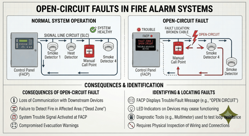
Open-Circuit Faults in Fire Alarm Systems
Why the Panel Trips Even When the Cable Isn’t Cut
Every commissioning engineer knows the routine open-circuit fault: a rodent has chewed through a cable, a contractor’s shovel has caught a duct bank, and the panel correctly reports “Open Circuit — Zone/Loop X.” But a large share of open-circuit faults logged on real GCC sites are reported against cable runs that are, physically, completely intact — no break, no cut, continuity confirmed with a simple multimeter. This article walks through why that happens, the exact voltage and resistance math the panel is using behind the scenes, and what to do about it on site.
1. Two Very Different Kinds of “Open Circuit”
A fire alarm panel does not actually “see” a broken wire. It sees a current or a polling response outside an expected window, and it reports that as an open circuit. That distinction matters, because there are two physically different faults that produce the identical panel message:
- Hard open circuit — a genuine break in the conductor (cut cable, snapped core, corroded-through wire). Resistance is effectively infinite.
- Resistive (“soft”) open circuit — the conductor is continuous end to end, but a connection somewhere in the circuit — a terminal, a crimp, a detector base, a junction box splice — has developed enough contact resistance that the current or voltage seen by the panel falls below its open-circuit threshold, even though a multimeter set to continuity/low-ohms across the whole run will often still beep.
The second case is the one that causes the most confusion in the field: the technician pulls continuity, gets a reading, and assumes the fault must be at the panel or the detector — when in fact the cable and every joint on it are the fault, just not in the way “cut cable” suggests.
2. How the Panel Actually Detects an Open Circuit
2.1 Conventional 2-wire zones (End-of-Line resistor supervision)
On a conventional zone, the panel supervises the loop with an End-of-Line (EOL) resistor — commonly 4.7 kΩ, 10 kΩ or 22 kΩ depending on the manufacturer — wired across the last device on the circuit. At 24 V DC nominal supply, a 10 kΩ EOL draws a standby current of about 2.4 mA. The panel’s fault logic accepts a narrow current window around that value as “normal”:
- Current drops toward zero (resistance rises sharply) → Open Circuit fault.
- Current rises well above normal (resistance collapses) → Short Circuit fault.
Any series resistance added anywhere in that loop — cable, terminals, detector bases — adds directly to the EOL value the panel is measuring. Under healthy conditions the cable itself contributes almost nothing (see Section 4), so it takes a real degraded connection to push the total high enough to trip the fault.
2.2 Addressable loops (voltage-drop / polling failure)
Addressable loops work differently: the panel polls each device individually over a two-wire loop, and every device needs a minimum terminal voltage to power its electronics and answer the poll. Here the fault is not really about the panel measuring “resistance” directly — it is about voltage drop along the loop starving a device (or a whole downstream segment past a loose joint) until it stops answering. The panel then reports that device, or the isolator segment behind it, as missing/open.
| Field Insight
This is the mechanism behind the classic “intermittent open circuit that clears itself” nuisance fault: a loose or oxidised terminal has enough contact area to pass current most of the time, but thermal expansion, vibration from nearby AHUs/generators, or a light touch during other works momentarily increases contact resistance past the trip point — then it relaxes back. The cable was never cut; the joint just crossed the voltage/resistance threshold for a moment. |
3. The Voltage Budget — Where the 12–24 V Comes In
Field devices in most GCC installations are specified to operate anywhere between 12 V and 24 V DC, and the panel is only guaranteed to deliver its nominal voltage under ideal conditions. Two things eat into that nominal supply before it reaches the farthest device:
- Battery-backed operation: under NFPA 72 / BS 5839 standby-battery conditions, panels are only required to maintain around 85% of nominal terminal voltage, not the full charged value.
- Cable and connection resistance: every metre of conductor and every terminal in series drops a small amount of voltage proportional to the current flowing (V = I × R).
Working a representative 24 V DC nominal system:
|
Parameter |
Value |
Basis |
| Panel terminal voltage, low-battery condition | 20.4 V DC | 85% of 24 V nominal |
| Minimum device operating voltage | 12.0 V DC | Lower end of typical 12–24 V device spec — confirm exact figure on the datasheet |
| Allowable voltage-drop budget (cable + joints) | 8.4 V DC | 20.4 V − 12.0 V |
That 8.4 V is the entire budget available for cable resistance, terminal resistance, and any margin for future degradation, all the way to the farthest device on the circuit. Once cable and joints together consume more than 8.4 V at the operating current, the last device(s) brown out, stop responding to polling, and the panel logs an open circuit — even with a perfectly continuous conductor.
For a 12 V nominal system the same logic applies at roughly half the numbers (approx. 10.2 V at the terminals under low-battery conditions, against a device minimum around 9–10 V), which is exactly why 12 V conventional circuits are only ever used for short, local runs — the voltage-drop budget is too thin for long cable runs, and 24 V is standard practice for larger commercial and high-rise loops.
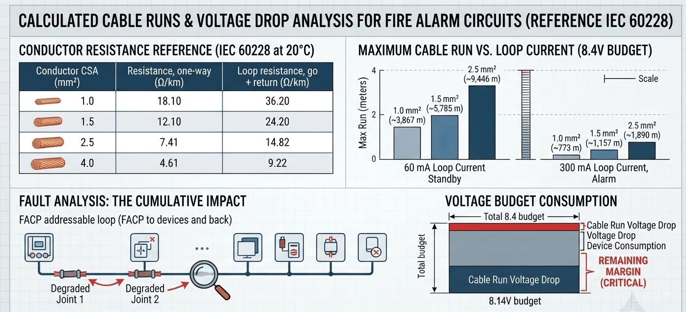
4. Cable Resistance: The Numbers Cable Alone Contributes
Standard copper conductor resistance (IEC 60228 reference values at 20°C) for the cable sizes most commonly used on fire alarm circuits in the region:
|
Conductor CSA |
Resistance, one-way (Ω/km) |
Loop resistance, go + return (Ω/km) |
| 1.0 mm² | 18.10 | 36.20 |
| 1.5 mm² | 12.10 | 24.20 |
| 2.5 mm² | 7.41 | 14.82 |
| 4.0 mm² | 4.61 | 9.22 |
Applying the 8.4 V budget from Section 3 gives the maximum cable run before voltage drop alone would starve the farthest device — shown here at two representative loop currents: a light standby/quiescent load (60 mA) and a heavier load with several notification appliances drawing current on the same circuit during alarm (300 mA):
|
Conductor CSA |
Max run @ 60 mA loop current |
Max run @ 300 mA loop current |
| 1.0 mm² | ≈ 3,867 m | ≈ 773 m |
| 1.5 mm² | ≈ 5,785 m | ≈ 1,157 m |
| 2.5 mm² | ≈ 9,446 m | ≈ 1,890 m |
The key takeaway: on a genuinely healthy cable, resistance from the conductor alone rarely causes an open-circuit trip — the numbers above are generous. The problem is almost never the cable run in isolation; it’s the cable run added to one or two degraded joints that eats into an already-tight budget on a long addressable loop feeding notification appliances near its rated limit.
5. Worked Example — Where the Margin Actually Disappears
Take a 1.5 mm² addressable loop run at 900 m, feeding a mix of detectors and sounder bases drawing a combined 300 mA in alarm. Cable resistance alone at 24.2 Ω/km × 0.9 km = 21.8 Ω, giving a voltage drop of 21.8 Ω × 0.3 A = 6.5 V — comfortably inside the 8.4 V budget, with 1.9 V (about 63 mΩ’s worth of resistance headroom, roughly 23% margin) to spare.
Now introduce one loose terminal screw or one oxidised crimp somewhere on that run, adding a modest 10 Ω of contact resistance — well within the range corrosion or a loose lug can realistically produce. Total resistance becomes 31.8 Ω, voltage drop rises to 9.5 V, and the budget is now exceeded by 1.1 V. The devices past that joint brown out, stop answering polls, and the panel raises Open Circuit / Device Missing on that loop — with the copper itself still 100% continuous from end to end.
| Why This Matters on Handover
This is precisely why a loop resistance test at commissioning (measuring actual end-to-end resistance with a calibrated loop tester, not just a pass/fail continuity beep) is not optional paperwork — it is the only way to know how much margin a given run actually has before a single degraded joint pushes it over the edge months later. |
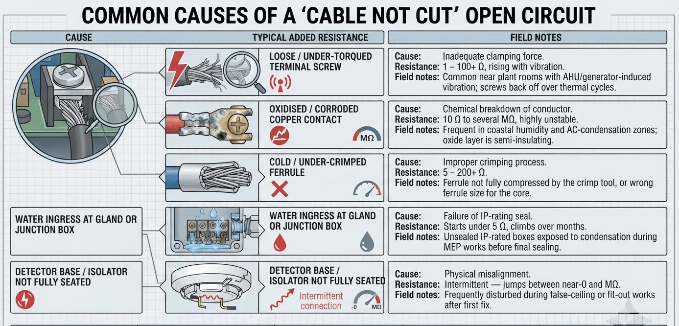
6. Common Causes of a “Cable Not Cut” Open Circuit
|
Cause |
Typical added resistance |
Field notes |
| Loose / under-torqued terminal screw | 1 – 100+ Ω, rising with vibration | Common near plant rooms with AHU/generator-induced vibration; screws back off over thermal cycles |
| Oxidised / corroded copper contact | 10 Ω to several MΩ, highly unstable | Frequent in coastal humidity and AC-condensation zones; oxide layer is semi-insulating |
| Cold / under-crimped ferrule | 5 – 200+ Ω | Ferrule not fully compressed by the crimp tool, or wrong ferrule size for the core |
| Water ingress at gland or junction box | Starts under 5 Ω, climbs over months | Unsealed IP-rated boxes exposed to condensation during MEP works before final sealing |
| Detector base / isolator not fully seated | Intermittent — jumps between near-0 and MΩ | Frequently disturbed during false-ceiling or fit-out works after first fix |
7. Solutions and Best Practice
7.1 Design stage
- Size conductors for the actual as-built run length, not a rule-of-thumb minimum — step up from 1.0 mm² to 1.5 mm² or 2.5 mm² on long addressable loops feeding multiple notification appliances.
- Design to a target of no more than 50–60% of the manufacturer’s maximum permitted loop resistance, leaving deliberate headroom for future joint degradation rather than designing right up to the limit.
- Place loop isolator modules at sensible intervals so a resistive fault is contained to a short segment instead of dropping an entire loop.
7.2 Installation
- Terminate to the manufacturer’s specified torque using a torque screwdriver, not “hand tight.”
- Use correctly sized ferrules with a calibrated crimp tool, and heat-shrink over every ferrule/joint exposed to humidity.
- Use IP66-rated glands and junction boxes in plant rooms, risers, and any area subject to condensation, and seal them before ceiling/wall close-up — not as a snagging-list afterthought.
- In coastal or high-humidity zones, specify tinned-copper conductors to slow galvanic corrosion at terminations.
7.3 Commissioning
- Record actual measured loop/zone resistance with a calibrated loop tester at handover, not just a continuity pass/fail — this baseline is what lets you spot a degrading joint before it becomes a hard fault.
- Carry out an insulation resistance (megger) test at the cable’s rated test voltage in addition to the loop resistance test, per NFPA 72 / BS 5839-1 commissioning requirements.
- Document the as-built cable-length and resistance figures per loop/zone in the O&M handover file, so future fault-finding can compare “expected vs measured” and localise a bad joint quickly instead of walking the whole run.
7.4 Maintenance (PPM)
- Re-torque terminal screws and re-check crimps on the scheduled PPM cycle, particularly in plant rooms and any area with sustained vibration.
- Trend loop resistance / device signal margin over successive PPM visits where the panel logs it — a joint creeping from, say, 8 Ω to 25 Ω over a year is an early warning, not a nuisance reading.
- Inspect and re-seal glands/junction boxes in humid or coastal-exposed locations at each PPM visit rather than waiting for a fault to appear.
8. Conclusion
An “open circuit” fault message is a symptom, not a diagnosis. On a real installation, it is at least as likely to originate from a degraded connection as from a cut cable — and the underlying cause is simple Ohm’s law: every joint in the circuit eats into a voltage-drop budget that is often only a few volts wide once low-battery operating conditions are accounted for. Sizing cable correctly for the actual run, terminating to spec, sealing against moisture, and measuring — not just testing continuity — at commissioning and PPM are what keep that budget intact for the life of the system.
