
On villa and hotel projects in Riyadh, Jeddah and across the GCC, KNX often lands on the ELV engineer’s desk late, after the mains are pulled and the lighting designer has a scene list. Most KNX problems I see on site are not product faults. They are a bus cable run as a ring, a line with too many devices, or an ETS project nobody can find at handover. This guide covers the KNX basics an ELV engineer needs: topology and addresses, devices, wiring rules and ETS6 commissioning, with a worked villa example.
Quick answer: KNX is an open, decentralised building automation bus. On twisted pair (KNX TP) one cable carries 30 V DC SELV power and data at 9,600 bit/s. Devices sit on lines of up to 64 per segment, each line with its own bus power supply, joined by couplers into areas. Sensors send telegrams to group addresses; actuators in the DB switch, dim or move the loads. Everything is configured in ETS: topology, parameters, group addresses, then a download to each device.
What Is KNX and Why ELV Engineers Should Know It
KNX is a manufacturer-independent standard for home and building control. It grew out of the older EIB, BatiBUS and EHS systems, and the KNX Association was formed in 1999. The standard is published as EN 50090 and as parts of ISO/IEC 14543-3, so devices from hundreds of manufacturers can share one bus and be programmed with one tool, ETS.
The key idea is that KNX has no master controller. A push button sends a short message, a telegram, to a group address, and every actuator listening to that group reacts. If the visualisation server fails, the wall switches still work. That is why KNX is popular for lighting, blinds and fan coils in villas, palaces, hotels and offices.
KNX runs on twisted pair (TP, the focus of this guide), on Ethernet as KNX IP, on 868 MHz radio as KNX RF, and on powerline. For the wider smart home picture, including Zigbee, Thread/Matter and Wi-Fi, see our smart home systems guide; this article goes one level deeper into KNX itself.
KNX Basics of Topology: Lines, Areas and Addresses
The basic unit of KNX TP is the line: one bus power supply (with a built-in choke that decouples the DC supply from the data) and its devices. Line couplers join lines to a main line, and area couplers join main lines to the backbone. Couplers also filter telegrams, so one floor’s traffic stays on that floor.
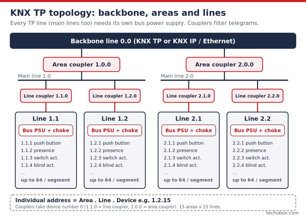
Every device has an individual address, Area.Line.Device, for example 1.2.15. Couplers take device number 0 (1.2.0 is the line coupler of line 1.2). Most villas use one area and two or three lines.
These are the TP1 limits I check on every design, as given in KNX basic course material and manufacturer datasheets:
| Limit (per line segment, TP1-64) | Value |
|---|---|
| Bus devices | 64 maximum |
| Total bus cable length | 1,000 m |
| Bus power supply to any device | 350 m |
| Between any two devices | 700 m |
| Bus voltage | 30 V DC SELV nominal; at least 21 V at each device |
| Data rate | 9,600 bit/s |
| Termination | None required |
Line repeaters can extend a line to four segments (each with its own supply), about 256 devices. Since 2019 KNX also defines TP1-256, allowing 256 devices on one line without repeaters when every device supports it. On mixed or older equipment, design to 64.
Pro tip: On a KNX IP project, a KNX IP router can work as the line or area coupler, so the backbone becomes the building LAN. It uses multicast (224.0.23.12, UDP port 3671 by default), so agree with the IT team that multicast is allowed on the KNX VLAN before you rely on it.
KNX Devices: What Goes on the Bus
KNX devices fall into four groups. Sensors send telegrams, actuators switch the real 230 V loads, and IP devices often need an auxiliary supply or PoE. I list them this way on the device schedule so the BOQ, DB layout and ETS project match.
| Group | Examples | Where installed |
|---|---|---|
| System devices | Bus power supply (160, 320 or 640 mA), line coupler, line repeater, USB or IP interface, IP router | DB or technical cabinet (DIN rail) |
| Sensors | Push buttons, room temperature sensors, presence and motion detectors, binary inputs, weather station | Rooms, ceilings, facade |
| Actuators | Switch, dimming, blind/shutter, fan coil and heating actuators, DALI gateways | DB (DIN rail) or ceiling void |
| Displays and gateways | Touch panels, visualisation servers, BACnet, Modbus or DALI gateways, AC interfaces | Walls, cabinet |
Each bus device has a programming button and LED, pressed during commissioning so ETS knows which physical device gets which address. Keep it reachable; an actuator hidden behind a packed DB adds hours on site.
My field advice: Plan actuators against the electrical drawings, not just the room list: one channel per switched circuit, dimmed circuit and curtain motor, plus spares. Check the LED driver dimming type (leading edge, trailing edge, DALI or 0-10 V) first. Most “flickering KNX dimmer” complaints I have seen were a driver and dimmer mismatch.
KNX Wiring Rules on Site
The bus cable is a twisted-pair cable with solid 0.8 mm conductors, normally two pairs and screened, often with a green sheath. The red core is bus positive and the black core is bus negative. The yellow and white pair is spare; some manufacturers allow it for an auxiliary supply, but I keep it unused unless the design says otherwise.
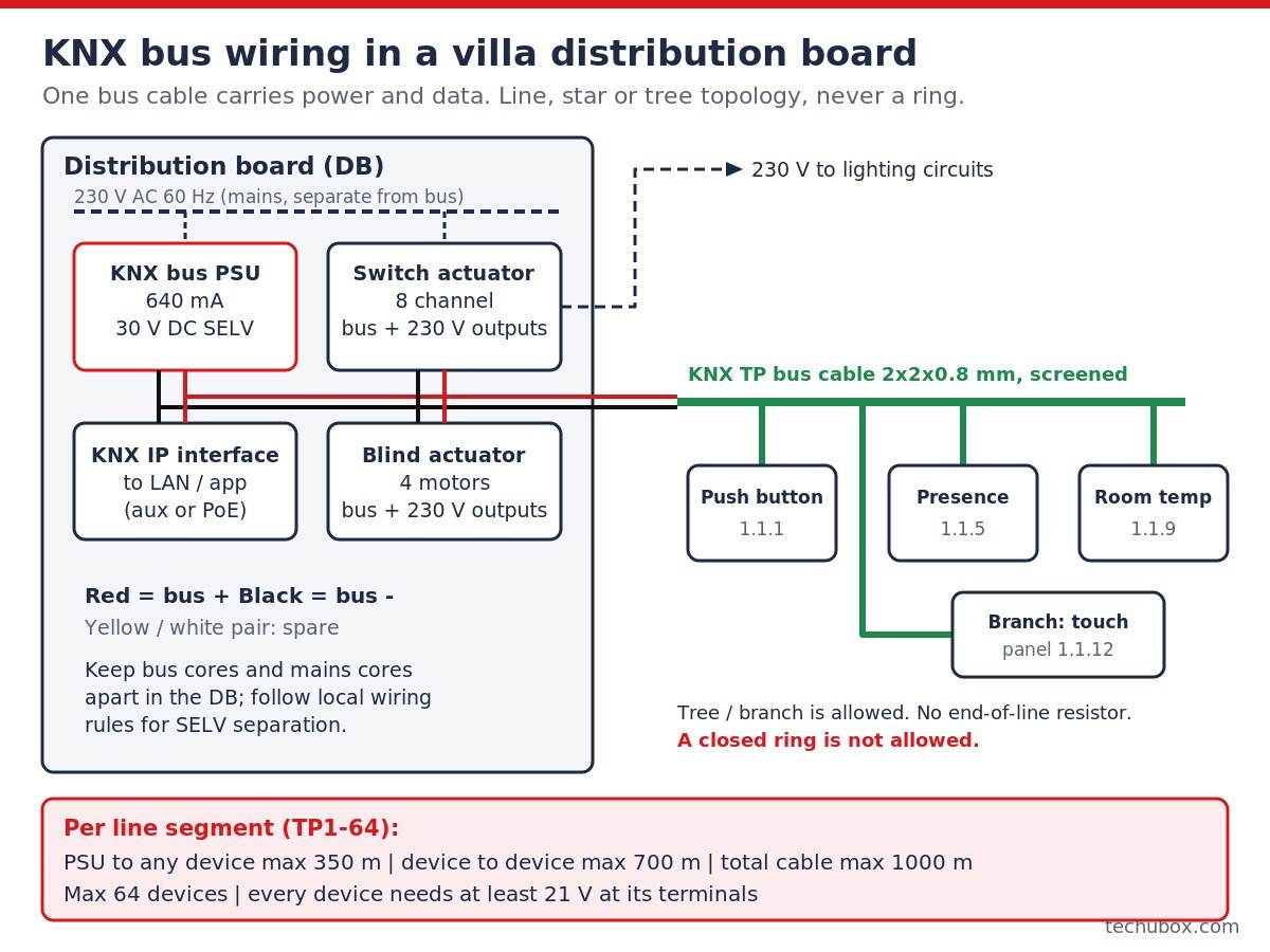
The rules I give installers before first fix:
- Free topology, no ring. Line, star and tree are all allowed. A closed ring is not. No end-of-line resistor is needed.
- Respect the distances. Keep the power supply central, not at one end with most devices bunched far away. Voltage drop is the real limit.
- One power supply per line. Two supplies on one line need a minimum distance and manufacturer approval; on villas I add a line instead.
- Separate from mains. KNX is SELV. Keep bus cores apart from mains cores in DBs and shared boxes, follow the local wiring regulations, and never use a spare mains core as the bus.
- Label and test. Mark both ends “KNX 1.1” and so on. Check continuity and polarity, and do insulation tests before devices are terminated.
- Screen and drain wire. Terminate them exactly as the cable and device manufacturers instruct, and never use them as a bus conductor.
In GCC plant rooms, heat matters. A DB packed with dimmers in an uncooled room can exceed the devices’ ambient rating in summer, so leave space between dimming actuators and specify ventilation.
Pro tip: Touch panels and IP routers often need a 24 V DC auxiliary supply. If it comes from another cabinet, size the cable with the Voltage Drop Calculator.
KNX vs Other Building Protocols
On a typical building KNX sits next to DALI lighting, Modbus meters and a BACnet BMS. This is how I explain the differences to clients:
| Protocol | Medium | Typical use | Programming | Watch out for |
|---|---|---|---|---|
| KNX TP | Dedicated twisted pair, 30 V DC bus power | Room control: lighting, blinds, fan coils, scenes | ETS (one tool for all brands) | Line limits, no ring, ETS licence size |
| KNX IP | Ethernet / LAN | Backbone, app and BMS interfaces | ETS | Multicast, VLAN design, security |
| DALI | Two-wire lighting bus | Individual luminaire control and status | Manufacturer or DALI tools; often via KNX-DALI gateway | Address limit per DALI line, gateway mapping |
| Modbus RTU / TCP | RS-485 or Ethernet | Energy meters, chillers, pumps, UPS | Register lists from each vendor | No standard object model; register maps vary |
| BACnet/IP | Ethernet / LAN | Central BMS, HVAC plant, integration | BMS vendor tools | Object mapping, device instances, network load |
A common split on GCC projects is KNX at room level and BACnet for the central BMS, joined by a gateway. Agree the points list (which group addresses the BMS reads and writes) early, because it drives both the ETS project and the BMS database. Our fire alarm, BMS, access control and CCTV integration guide shows how these interfaces are usually organised.
KNX Group Addresses Explained
Individual addresses say where a device is; group addresses say what it does. A rocker sends “on” to 1/0/1, the majlis light channel listens to 1/0/1, and a status group 1/0/2 reports the real state to panels and apps.
ETS supports a three-level Main/Middle/Sub structure (0 to 31, 0 to 7, 0 to 255). Pick one convention, write it in the design report, and stick to it. Mine for villas:
- Main group = function: 1 Lighting, 2 Blinds and curtains, 3 HVAC, 4 Scenes, 5 Alarms and technical, 6 Status and feedback.
- Middle group = floor: 0 Ground floor, 1 First floor, 2 Roof, 7 Outdoor.
- Sub group = item, named in plain words, for example “GF Majlis Ceiling Light Switch”.
Good names matter more than numbers: “GA 1/0/17” means nothing two years later; “GF Kitchen Downlights Dim Value” does.
KNX Commissioning with ETS6 Step by Step
ETS (Engineering Tool Software) is the official KNX tool. The current version, ETS6, comes in three licence sizes: Lite (unlimited projects, up to 20 devices each), Home (one project, up to 64 devices) and Professional (no limits). Without a licence it runs as a demo limited to 5 devices per project. Check the device count before the client buys a licence; a villa can pass 64 devices quickly.
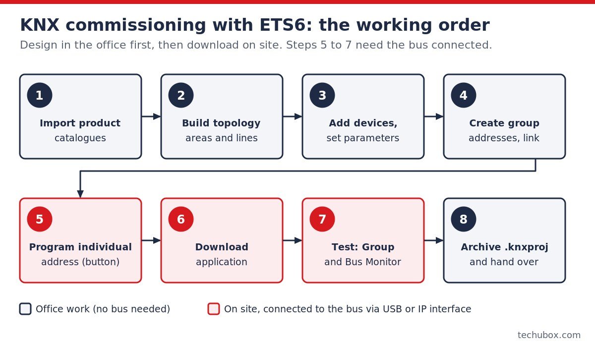
- Import product catalogues from each manufacturer into ETS.
- Build the topology (areas, lines) and the building structure (floors, rooms, DBs) to match the drawings.
- Add devices and set parameters: channel functions, dimming curves, blind travel times, detector sensitivity.
- Create group addresses and link each device’s communication objects to them.
- Program the individual address: connect through a USB or IP interface, start the program command and press the device’s programming button.
- Download the application to each device; partial downloads are quicker after small changes.
- Test with the Group Monitor while pressing buttons and walking past detectors.
- Archive and hand over the .knxproj file and project password.
Devices with KNX Secure (Data Secure on the bus, IP Secure on the LAN) come with a device certificate, often a QR code, that ETS needs during commissioning. Keep those certificates and the project password safe.
My field advice: Never let the only copy of the ETS project live on a technician’s laptop. I have been called to villas where the integrator left and nobody could change a scene. Make the archived project a contract handover item, like as-built drawings.
Practical Example: G+1 Villa in Riyadh
A new two-storey villa: lighting, curtains and AC fan coils on KNX, an app for the owner, and integration with the CCTV and intercom. Device counts from the design:
| Device | Ground floor (line 1.1) | First floor (line 1.2) |
|---|---|---|
| Push buttons with temperature sensor | 16 | 20 |
| Presence detectors | 6 | 8 |
| Switch actuators (16-channel) | 2 | 2 |
| Dimming actuator | 1 | 1 |
| Blind actuator (8-channel) | 1 | 1 |
| Fan coil actuators | 4 | 5 |
| KNX IP router (line coupler) | 1 | 1 |
| Total bus devices | 31 | 38 |
Step 1: lines. 69 devices exceed one 64-device segment, so I split by floor: line 1.1 (ground) and line 1.2 (first). The two KNX IP routers act as line couplers 1.1.0 and 1.2.0 on the villa LAN.
Step 2: power budget. For early sizing I allow about 10 mA per bus-powered device, then confirm from datasheets because touch panels and some detectors draw more. Ground floor: 31 x 10 mA = 310 mA. First floor: 38 x 10 mA = 380 mA. A 640 mA supply per line runs at about 48% and 59% load, with room for future devices. I keep each line below about 80% of the supply rating.
Step 3: cable. About 350 to 450 m of bus cable per floor in a tree from the floor DB, furthest device about 60 m from the supply: well inside the limits.
Step 4: network. The KNX IP routers, visualisation server and gateway get their own VLAN with fixed IP addresses. A /27 subnet is plenty; plan it with the IP Subnet & VLAN Planner, and size the technical rack (router, switch, NVR, KNX server, UPS) with the Rack Layout & U Planner. The Cat6 outlets for touch panels and access points belong in the Structured Cabling Designer schedule.
Step 5: licence. At 69 devices, the project is over the ETS6 Home limit of 64, so it needs ETS6 Professional. This is normally the integrator’s licence, not the owner’s.
Common KNX Mistakes and Troubleshooting
| Symptom | Likely cause | Fix |
|---|---|---|
| Whole line dead, no device responds | Bus power supply off, short circuit, or polarity swapped at a device | Measure bus voltage at the supply and at a device; split the line to find the short |
| Devices at the far end act randomly | Voltage below 21 V from long runs or too many devices | Measure at the device; move the supply, add a line or a repeater |
| LEDs flicker when dimmed | Dimmer mode does not match the LED driver | Set leading or trailing edge to match, or use DALI |
| Nobody can change scenes after handover | No archived ETS project or lost password | Make the .knxproj and password a contract handover item |
KNX with CCTV, Access Control and Fire Alarm
KNX is a comfort system. It can take a “fire mode” signal from a fire alarm relay through a binary input, for example to switch corridor lights on, but it must never carry life-safety functions. Fire alarm sounders, door release on escape routes and lift recall stay hard-wired through the fire alarm system. NFPA 72 and BS 5839-1 give guidance on these interfaces; check the current edition and the local authority (Civil Defense in Saudi Arabia) before you finalise the design. See access control and fire alarm integration for the door side.
CCTV and intercom usually integrate at IP level, for example a camera pop-up on a door ring. Keep KNX IP devices on their own VLAN; our CCTV cybersecurity guide applies equally to KNX routers and servers.
Frequently Asked Questions
What voltage does the KNX bus use?
A nominal 30 V DC SELV supply, often quoted as 29 V. Each device must see at least 21 V at its terminals.
How many devices can be connected to one KNX line?
Up to 64 per segment on TP1-64; about 256 with line repeaters, or 256 on one line with TP1-256 if every device supports it.
Can I use Cat6 instead of KNX cable?
No. Use KNX bus cable with solid 0.8 mm conductors. Cat6 conductors are thinner, and the distance limits assume KNX-specified cable.
Which ETS licence do I need?
ETS6 Lite covers projects up to 20 devices, Home one project up to 64, and Professional has no limits. Count every bus device, couplers included.
Can KNX connect to a BMS?
Yes, usually through a KNX-BACnet or KNX-Modbus gateway, or a BMS driver for KNX IP. Agree the points list early.