
On almost every ELV project I hand over in Riyadh, Jeddah or Dammam, the network is where the snags hide. Cameras, door controllers and BMS controllers end up on one flat 192.168.1.x network, and the NVR can reach the internet. MikroTik routers are common in villas, compounds and small commercial buildings across KSA and the GCC because they are affordable and very capable, but RouterOS VLAN setup has changed a lot, and many older tutorials still show the RouterOS v6 way. This guide gives a complete MikroTik VLAN configuration for CCTV, access control and BMS, written for RouterOS 7 with bridge VLAN filtering, with the full CLI and the matching WinBox steps.
Quick answer: On RouterOS 7, create one bridge with vlan-filtering=no, add the trunk port with frame-types=admit-only-vlan-tagged and each access port with its pvid, add one /interface/bridge/vlan entry per VLAN with the trunk and the bridge itself as tagged members, then create a VLAN interface on the bridge for each VLAN with its gateway IP, DHCP server and firewall rules. Enable vlan-filtering=yes last, in Safe Mode or from a port outside the bridge, so you do not lock yourself out.
Version note: Commands and menu paths below were checked against the official RouterOS 7 manual (the v7.26 edition at manual.mikrotik.com, which replaced help.mikrotik.com). They suit RouterOS 7.16 or later; most of it also works on earlier 7.x releases. They do not apply to RouterOS v6 “switch menu” VLAN setups.
Why VLANs Matter on an ELV Network
A VLAN splits one physical switch into several logical networks. For ELV systems that gives three wins. Heavy, constant camera traffic stays away from door and BMS controllers. A compromised camera cannot scan the access control server. And the firewall gets clear boundaries to enforce, such as “cameras talk to the NVR and nothing else”.
If VLANs are new to you, start with our VLAN for CCTV systems guide, which explains access ports, trunk ports and tagging without any vendor syntax. This article is the MikroTik implementation of those ideas.
The Worked Example: VLAN Plan for a Small ELV Building
The example is a typical G+2 commercial building or compound gatehouse: 12 IP cameras and an NVR, 4 door controllers with an access control server, a KNX IP router and a few BACnet/IP DDC controllers, all fed from one managed PoE switch. The router is a MikroTik with a built-in switch chip, for example an RB5009. Here is the VLAN plan I would put in the network design document.
| VLAN | Name | Subnet | Gateway | DHCP pool | Devices |
|---|---|---|---|---|---|
| 10 | CCTV | 10.10.10.0/24 | 10.10.10.1 | .100 to .199 | IP cameras, NVR (10.10.10.10) |
| 20 | ACCESS | 10.10.20.0/24 | 10.10.20.1 | .100 to .199 | Door controllers, ACS server (10.10.20.10) |
| 30 | BMS | 10.10.30.0/24 | 10.10.30.1 | .100 to .199 | KNX IP router, DDC controllers |
| 99 | MGMT | 10.10.99.0/24 | 10.10.99.1 | .100 to .149 | Switch (10.10.99.2), engineer laptop, operator PC |
A /24 per VLAN is generous for this size, but it keeps the third octet equal to the VLAN ID, which saves time on site. If you need tighter subnets, size them with the IP Subnet Calculator, and check the PoE switch can power all cameras and readers with the PoE Budget Calculator.
| Router port | Role | VLAN setting |
|---|---|---|
| ether1 | WAN to ISP | Not in the bridge |
| ether2 | Trunk to managed PoE switch (port 24) | Tagged 10, 20, 30, 99 |
| ether3 | NVR | Access, untagged VLAN 10 |
| ether4 | Engineer laptop in the rack | Access, untagged VLAN 99 |
| ether5 | Rescue port | Not in the bridge, 192.168.88.1/24 |
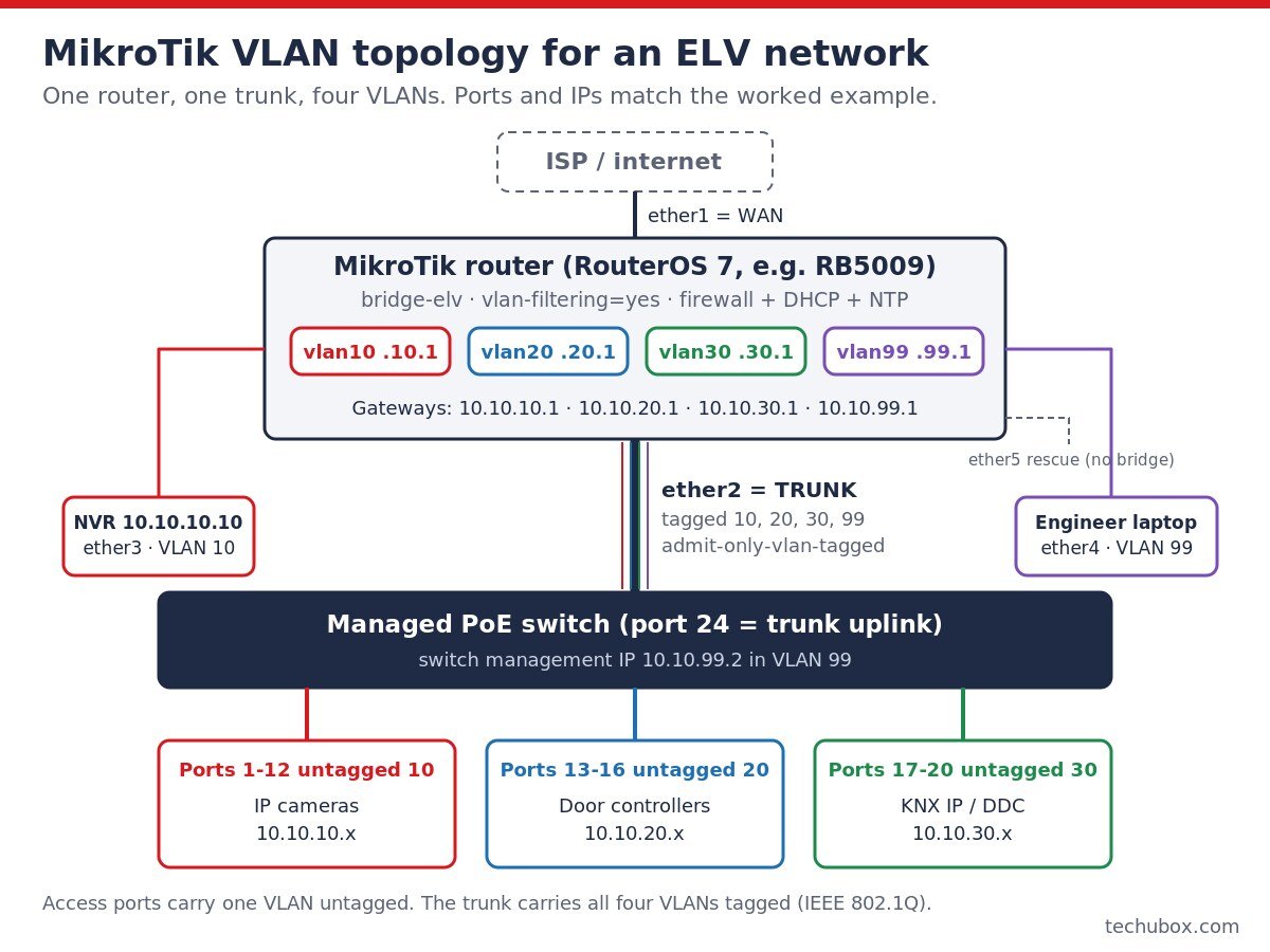
My field advice: Draw this diagram before you touch the router, and stick it inside the rack door. You can draw it quickly in the Network & CCTV Designer. When the maintenance company visits two years later, the diagram is what saves the system.
How Bridge VLAN Filtering Works in RouterOS 7
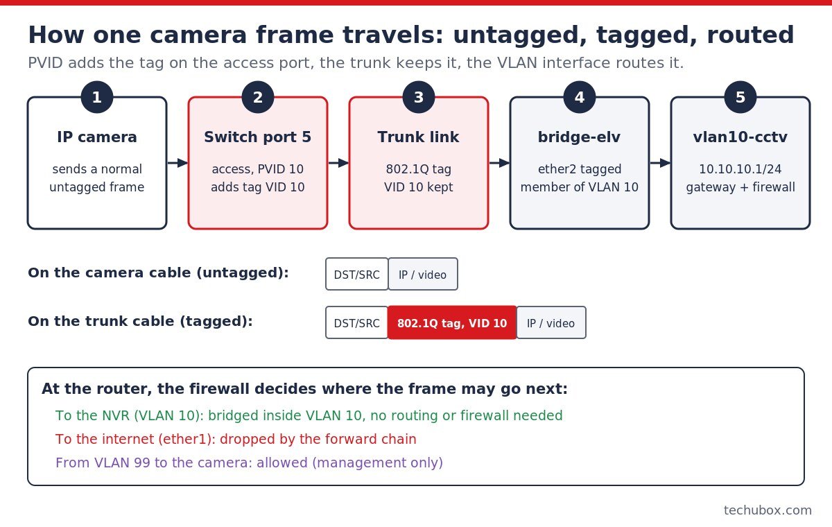
In RouterOS v6 videos you often see a VLAN interface created on a physical port and then bridged, or VLANs configured in the old switch menu. The current MikroTik manual recommends bridge VLAN filtering instead: one bridge that behaves like a VLAN-aware switch. Four ideas carry the whole configuration:
- PVID on a bridge port puts untagged frames arriving on that port into a VLAN. This is how an access port works.
- The bridge VLAN table (
/interface/bridge/vlan) lists which ports may carry each VLAN, and whether they send it tagged or untagged. - frame-types and ingress-filtering stop the wrong kind of traffic coming in: tagged only on the trunk, untagged only on access ports. Ingress filtering is on by default for bridge ports in RouterOS 7.
- The bridge itself is a port (the CPU port). To route a VLAN, the bridge must be a tagged member of it, and a VLAN interface on the bridge gives the router its gateway IP in that VLAN.
Hardware offload note: According to the MikroTik manual, devices with a Marvell Prestera switch chip (CRS3xx, CRS5xx, CCR2116 and others) and, since RouterOS 7, some other chips such as the 88E6393X in the RB5009 and the MT7621 in the hEX can run bridge VLAN filtering in hardware. On other models, enabling VLAN filtering moves switching to the CPU, and the manual points you to a model-specific switch-chip method instead. Check the H flag in /interface/bridge/port/print after the change, and check the manual’s hardware offloading table for your exact model. Routing between VLANs still uses the CPU on most models; this design keeps that light because cameras and the NVR share VLAN 10.
Step 1: Prepare a Rescue Port and Back Up
I start every MikroTik VLAN job by taking ether5 out of any bridge and giving it a fixed IP. If something goes wrong, I plug in there and still reach the router. Take a backup first (Files in WinBox, or /system/backup/save) and export the current config.
# Name the router and keep ether5 outside any bridge as a rescue port
/system/identity
set name=ELV-CORE-RTR
/ip/address
add address=192.168.88.1/24 interface=ether5 comment="rescue port - not in bridge"
# Backup and export before you change anything
/system/backup/save name=before-vlan
/export file=before-vlan
If the router still has its default configuration, ether5 is already in the default bridge: remove it under Bridge > Ports, or start clean with /system/reset-configuration no-defaults=yes and connect by MAC address in WinBox. Step 6 builds a full firewall either way.
Step 2: Create the Bridge and Add Ports (VLAN Filtering Off)
/interface/bridge
add name=bridge-elv vlan-filtering=no comment="ELV VLAN bridge"

/interface/bridge/port
add bridge=bridge-elv interface=ether2 frame-types=admit-only-vlan-tagged comment="TRUNK to PoE switch"
add bridge=bridge-elv interface=ether3 pvid=10 frame-types=admit-only-untagged-and-priority-tagged comment="NVR"
add bridge=bridge-elv interface=ether4 pvid=99 frame-types=admit-only-untagged-and-priority-tagged comment="Engineer laptop"
WinBox: Bridge > Bridge tab > New. Name it bridge-elv, leave VLAN Filtering unticked, OK. Then Bridge > Ports > New for each port: Interface ether2, VLAN tab, Frame Types “admit only VLAN tagged”. For ether3 and ether4 set PVID 10 or 99 and Frame Types “admit only untagged and priority tagged”.
Step 3: Build the Bridge VLAN Table
Each VLAN gets one entry with the trunk and the bridge as tagged members. You do not need to list the access ports: RouterOS adds them as untagged members automatically from their PVID.
/interface/bridge/vlan
add bridge=bridge-elv tagged=bridge-elv,ether2 vlan-ids=10 comment="CCTV"
add bridge=bridge-elv tagged=bridge-elv,ether2 vlan-ids=20 comment="ACCESS"
add bridge=bridge-elv tagged=bridge-elv,ether2 vlan-ids=30 comment="BMS"
add bridge=bridge-elv tagged=bridge-elv,ether2 vlan-ids=99 comment="MGMT"
Pro tip: Never put several VLAN IDs in one entry that also has untagged access ports. The MikroTik manual warns this can leak tagged traffic out of the wrong access port. Several IDs in one entry are fine for tagged trunk members only.
WinBox: Bridge > VLANs > New. Bridge bridge-elv, VLAN IDs 10, Tagged: bridge-elv and ether2. Repeat for 20, 30 and 99.
Step 4: VLAN Interfaces, Gateway IPs and DHCP per VLAN
Now the router gets a foot in each VLAN. The VLAN interfaces sit on the bridge, not on ether2. From RouterOS 7.16 the router also adds the bridge as a tagged member dynamically when you do this, but adding it yourself in Step 3 keeps the config clear on any 7.x version.
# VLAN interfaces on the bridge
/interface/vlan
add interface=bridge-elv name=vlan10-cctv vlan-id=10
add interface=bridge-elv name=vlan20-access vlan-id=20
add interface=bridge-elv name=vlan30-bms vlan-id=30
add interface=bridge-elv name=vlan99-mgmt vlan-id=99

# Gateway IPs
/ip/address
add address=10.10.10.1/24 interface=vlan10-cctv
add address=10.10.20.1/24 interface=vlan20-access
add address=10.10.30.1/24 interface=vlan30-bms
add address=10.10.99.1/24 interface=vlan99-mgmt

# Address pools
/ip/pool
add name=pool-cctv ranges=10.10.10.100-10.10.10.199
add name=pool-access ranges=10.10.20.100-10.10.20.199
add name=pool-bms ranges=10.10.30.100-10.10.30.199
add name=pool-mgmt ranges=10.10.99.100-10.10.99.149

# One DHCP server per VLAN
/ip/dhcp-server
add name=dhcp-cctv interface=vlan10-cctv address-pool=pool-cctv lease-time=1d disabled=no
add name=dhcp-access interface=vlan20-access address-pool=pool-access lease-time=1d disabled=no
add name=dhcp-bms interface=vlan30-bms address-pool=pool-bms lease-time=1d disabled=no
add name=dhcp-mgmt interface=vlan99-mgmt address-pool=pool-mgmt lease-time=8h disabled=no

# DHCP options: ELV VLANs get gateway + NTP, MGMT also gets DNS
/ip/dhcp-server/network
add address=10.10.10.0/24 gateway=10.10.10.1 ntp-server=10.10.10.1
add address=10.10.20.0/24 gateway=10.10.20.1 ntp-server=10.10.20.1
add address=10.10.30.0/24 gateway=10.10.30.1 ntp-server=10.10.30.1
add address=10.10.99.0/24 gateway=10.10.99.1 dns-server=10.10.99.1 ntp-server=10.10.99.1

# Router keeps time from the internet and serves it to the VLANs
/system/ntp/client
set enabled=yes servers=pool.ntp.org
/system/ntp/server
set enabled=yes
I enable the router’s NTP server and hand it out by DHCP. Cameras and door controllers without correct time produce recordings and event logs that are hard to use as evidence, and these VLANs have no internet to reach a public time server.
WinBox: Interfaces > VLAN > New (Name, VLAN ID, Interface bridge-elv). IP > Addresses > New for each gateway. IP > DHCP Server > DHCP Setup runs a wizard per VLAN interface that creates the pool, server and network in one go; then edit the Networks tab to set NTP and remove DNS where not wanted.
My field advice: Use DHCP to bring cameras up during commissioning, then make every lease static (IP > DHCP Server > Leases > Make Static, or set fixed IPs on the devices). The NVR, ACS server and BMS supervisor must never see an address change. Identify unknown devices from the lease MAC with the MAC Address Lookup tool.
Step 5: WAN, NAT and Interface Lists
Interface lists make the firewall readable. ELV holds the three systems VLANs, MGMT holds VLAN 99, and WAN holds ether1. If your router kept its default configuration, the WAN and LAN lists already exist; only add what is missing.
/interface/list
add name=WAN
add name=ELV
add name=MGMT
/interface/list/member
add list=WAN interface=ether1
add list=ELV interface=vlan10-cctv
add list=ELV interface=vlan20-access
add list=ELV interface=vlan30-bms
add list=MGMT interface=vlan99-mgmt

# Internet on ether1 (use a static IP or PPPoE if your ISP needs it)
/ip/dhcp-client
add interface=ether1 disabled=no
/ip/firewall/nat
add chain=srcnat action=masquerade out-interface-list=WAN comment="NAT to internet"

# DNS for the management VLAN only
/ip/dns
set allow-remote-requests=yes
Step 6: Inter-VLAN Firewall Rules for CCTV, Access Control and BMS
This is the policy I apply on most ELV projects. It is deny by default: anything not explicitly allowed is dropped.
| From | To | Policy |
|---|---|---|
| CCTV VLAN 10 | NVR | Allowed (same VLAN, switched, no firewall involved) |
| CCTV VLAN 10 | Internet, other VLANs | Blocked |
| ACS server 10.10.20.10 | NVR 10.10.10.10 | Allowed on listed TCP ports only (video pop-up integration) |
| BMS VLAN 30 | Internet, other VLANs | Blocked |
| MGMT VLAN 99 | All VLANs, router, internet | Allowed |
| Any ELV VLAN | Router | NTP and ping only (DHCP works without a rule) |
/ip/firewall/filter
# ---- INPUT: traffic to the router itself ----
add chain=input action=accept connection-state=established,related,untracked comment="IN: established"
add chain=input action=drop connection-state=invalid comment="IN: drop invalid"
add chain=input action=accept protocol=icmp comment="IN: ICMP"
add chain=input action=accept in-interface-list=MGMT comment="IN: management from VLAN 99"
add chain=input action=accept in-interface=ether5 comment="IN: rescue port"
add chain=input action=accept protocol=udp dst-port=123 in-interface-list=ELV comment="IN: NTP for ELV devices"
add chain=input action=drop comment="IN: drop everything else"
# ---- FORWARD: traffic through the router ----
add chain=forward action=accept connection-state=established,related,untracked comment="FWD: established"
add chain=forward action=drop connection-state=invalid comment="FWD: drop invalid"
add chain=forward action=accept in-interface-list=MGMT comment="FWD: VLAN 99 to all VLANs and internet"
add chain=forward action=accept protocol=tcp src-address=10.10.20.10 dst-address=10.10.10.10 dst-port=80,443,554 comment="FWD: ACS server to NVR"
add chain=forward action=drop comment="FWD: drop everything else (ELV VLANs isolated, no internet)"
The ports in the ACS-to-NVR rule (80, 443, 554 for RTSP) are only an example. Use exactly the ports in your VMS or access control integration document; some vendors use their own SDK port. Rules are checked from the top, so the final drop must stay last. With this policy the router can be managed only from VLAN 99 and the rescue port.
WinBox: IP > Firewall > Filter Rules > New. On the General tab set Chain, Connection State, In. Interface List; on the Action tab set accept or drop; add a comment for each. Drag rules into the order shown.
Step 7: Enable VLAN Filtering Safely
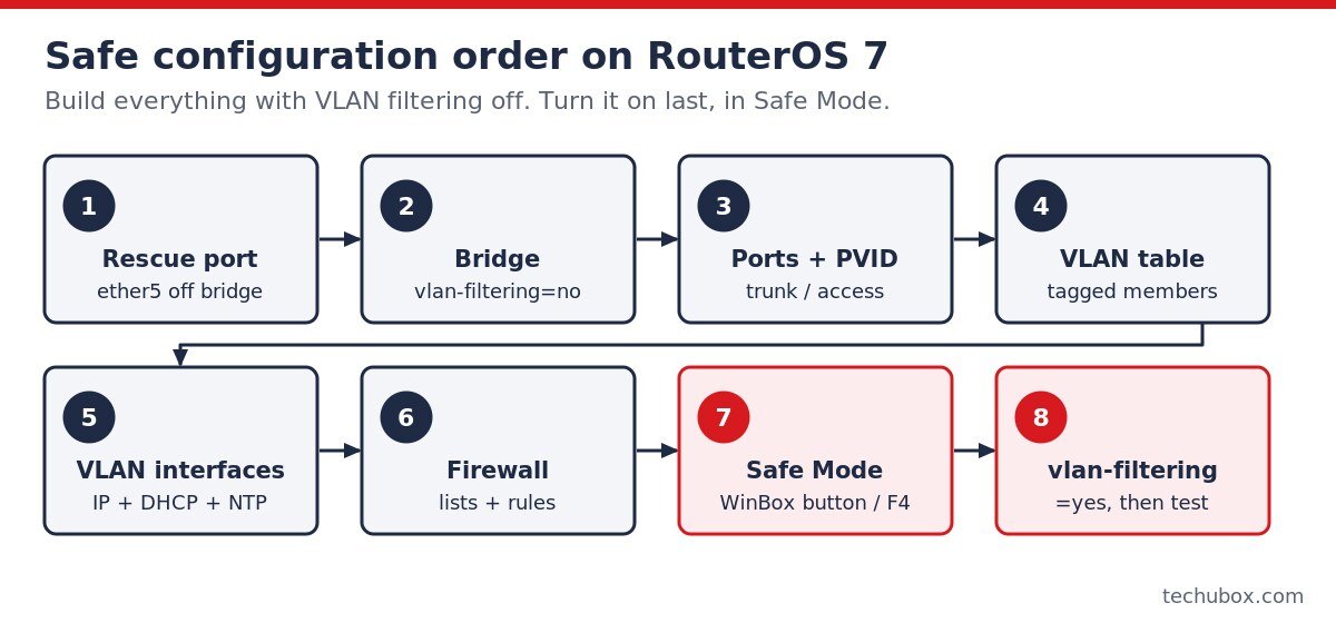
Connect from the rescue port (ether5). Then press Safe Mode in WinBox (or Ctrl+X / F4 in the terminal). If your session drops, RouterOS rolls back the changes made in Safe Mode after a timeout (the manual gives the TCP timeout as 9 minutes). Click it again to keep the changes once access is confirmed.
# In Safe Mode (WinBox Safe Mode button, or Ctrl+X in the terminal)
/interface/bridge
set bridge-elv vlan-filtering=yes
# Optional hardening from the MikroTik manual: no untagged access to the bridge (CPU port)
set bridge-elv frame-types=admit-only-vlan-tagged
The second command stops untagged traffic reaching the router through the bridge on the default VLAN 1, so the router answers only on its VLAN interfaces. The manual notes that changing VLAN filtering can reset the switch chip, so every port drops for a moment. On a live site, use a maintenance window and warn the guard room.
Step 8: Configure the Managed PoE Switch
The switch side must mirror the router exactly. Menu names differ by brand, but the settings are the same on any 802.1Q switch:
| Switch port | Mode | VLANs |
|---|---|---|
| 24 (uplink to MikroTik ether2) | Trunk | Tagged 10, 20, 30, 99; remove VLAN 1 if the switch allows it |
| 1 to 12 | Access | Untagged 10, PVID 10 |
| 13 to 16 | Access | Untagged 20, PVID 20 |
| 17 to 20 | Access | Untagged 30, PVID 30 |
| Management interface | VLAN 99 | 10.10.99.2/24, gateway 10.10.99.1 |
Change the switch management VLAN to 99 last, from a laptop on VLAN 99, or you will lose the switch the same way you can lose the router. A MikroTik CRS3xx switch running RouterOS uses the same bridge VLAN filtering method, plus one VLAN 99 interface for its own management.
Step 9: Verify Before You Leave Site
/interface/bridge/vlan/print
/interface/bridge/port/print
/interface/bridge/host/print where !local
/ip/dhcp-server/lease/print
/ip/firewall/filter/print stats
/system/ntp/client/print
Then test from real devices: a camera gets a 10.10.10.x lease and shows on the NVR; a ping from a camera VLAN laptop to 8.8.8.8 fails; the engineer laptop on VLAN 99 reaches the switch, the NVR web page and the internet; the counters on the final drop rules grow when you try what should be blocked.
NVR Remote View Without Opening the CCTV VLAN
Clients always ask to watch cameras on the phone. With this design, the cameras and NVR have no internet, so vendor P2P cloud apps will not work, and that is intended. My preferred option is a VPN on the MikroTik (WireGuard is built into RouterOS 7) that lands remote users in VLAN 99, from where they reach the NVR. Opening NVR ports to the internet with port forwarding is the option I avoid. If the client insists on the vendor cloud, allow only the NVR’s IP out to the internet with one specific rule above the final drop, keep the cameras blocked, and keep NVR firmware current. Our CCTV cybersecurity guide covers the hardening checklist.
Troubleshooting MikroTik VLAN Problems
| Symptom | Likely cause | Fix |
|---|---|---|
| Lost access right after vlan-filtering=yes | You were connected through an untagged bridge port with no VLAN 99 path | Use the rescue port or wait for Safe Mode rollback; add VLAN 99 to the trunk and bridge |
| Cameras get no DHCP lease | Switch port PVID wrong, or VLAN missing on the trunk at one end | Compare switch port VLANs with /interface/bridge/vlan/print; check the DHCP server is not disabled |
| Devices get an IP but cannot reach the gateway | Bridge not a tagged member of that VLAN | Add bridge-elv to the tagged list of the VLAN entry |
| Camera reachable from the wrong VLAN | Several VLAN IDs in one entry with untagged ports, or firewall rule order | One entry per VLAN; move the final drop rules to the bottom |
| Low throughput, high CPU after the change | Model has no hardware-offloaded VLAN filtering | Check the H flag; follow the manual’s switch-chip method for that model |
| ACS video pop-up fails | Integration port not in the ACS-to-NVR rule | Read the counters, check the vendor port list, add the port |
| KNX IP routing (multicast) not working across devices | Multicast is blocked between VLANs or flooded | Keep KNX IP devices in one VLAN; see our KNX basics guide |
Frequently Asked Questions
Do I still use the switch menu for VLANs on RouterOS 7?
For most current models, no. The manual recommends bridge VLAN filtering, which is hardware offloaded on CRS3xx and several other chips in RouterOS 7. Some older RouterBOARD models still need the switch-chip method for wire speed; check the manual for your model.
Should the NVR be in the same VLAN as the cameras?
For small and medium systems, yes. Camera streams then stay inside the switch and never load the router. On large sites with a separate server VLAN, route between them on a router or L3 switch that can handle the full camera bandwidth.
Why add the bridge as a tagged member?
The bridge is the router’s own CPU port. Without it in the VLAN, the VLAN interface never receives traffic, so devices cannot reach their gateway, DHCP or NTP.
Can I manage the router from the CCTV VLAN?
Not with this policy, and I recommend keeping it that way. Management stays on VLAN 99 and the rescue port, so a compromised camera cannot even reach the WinBox login.
References: MikroTik RouterOS manual: Bridging and Switching (bridge VLAN filtering, hardware offloading), Bridge VLAN Table, Firewall Filter and Console (Safe Mode). Always test a new configuration on your exact model and RouterOS version before going live.