Guide to Subsea Monitoring Systems & Underwater Surveillance
Subsea Monitoring Systems: A Complete Guide to Underwater Surveillance & Communication Links to Surface
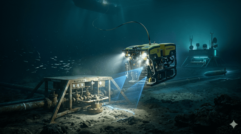
The ocean’s depths present one of the most challenging environments for human engineering. As global industries expand into deep-water oil and gas extraction and offshore wind farms, the need for reliable, real-time data from the seafloor becomes critical. A subsea monitoring system acts as the eyes and ears for offshore operators, providing continuous visual and sensory data from thousands of meters below the surface. This technology is a fundamental pillar of modern maritime infrastructure, ensuring the safety of subsea assets, pipeline integrity, and security of international waters.
A shift towards autonomous operations and predictive maintenance drives the growing demand for real-time underwater surveillance. Historically, subsea inspections involved costly, weather-dependent vessel deployments and diver missions. Today, integrated monitoring solutions offer 24/7 observation, enabling early detection of minor leaks or structural anomalies before they escalate into catastrophic environmental disasters. This comprehensive guide explores the intricate architecture of these systems, from high-definition cameras capturing the abyss to sophisticated communication links bridging the seafloor and the surface.
What is a Subsea Monitoring System?
At its core, a subsea monitoring system is an integrated network of sensors, cameras, and data processing units designed for autonomous or semi-autonomous operation in submerged environments. Unlike surface monitoring, subsea systems must endure extreme hydrostatic pressure, corrosive saltwater, and complete darkness. Their primary purpose is to provide situational awareness and structural health data for underwater assets such as wellheads, pipelines, manifolds, and power cables.
The typical system architecture comprises three main segments: the subsea acquisition layer (sensors and cameras), the transmission layer (cables and modems), and the topside control layer (servers and human-machine interfaces). While surface monitoring often uses radio waves and Wi-Fi, water physics necessitates a distinct approach to communication and power. Subsea systems are engineered with specialised materials like titanium and marine-grade stainless steel to ensure longevity in a naturally degrading environment.
Applications are diverse. In oil and gas, they facilitate leak detection and valve position monitoring. For renewable energy, they track subsea power cable conditions and turbine foundation integrity. Environmental researchers use them to monitor ocean temperatures, currents, and marine life, while port authorities deploy them as part of an underwater surveillance system to protect critical harbour infrastructure from intrusions.
|
Application Area |
Primary Monitoring Goal |
Key Technologies Used |
|
Oil & Gas |
Leak detection & asset integrity |
Thermal cameras, pressure sensors, and acoustic leak detectors |
|
Offshore Wind |
Cable health & foundation stability |
Fibre optic sensing (DAS/DTS), strain gauges |
|
Marine Research |
Environmental & biological data |
ADCPs, chemical sensors, 4K fixed cameras |
|
Port Security |
Intrusion detection & hull inspection |
Diver detection sonar, ROV-mounted CCTV |
Key Components of a Subsea Monitoring System
Building a reliable subsea monitoring system requires a modular approach, with each component rated for specific depth and environmental conditions. All equipment must be pressure-compensated or housed in robust pressure vessels to prevent catastrophic failure.
Subsea Cameras and Imaging Systems
The visual component is critical for any underwater surveillance system. Cameras are categorised by deployment: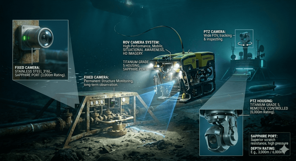
- Fixed Cameras: Permanently mounted on subsea structures for long-term observation of specific points.
- PTZ (Pan-Tilt-Zoom) Cameras: Remotely controlled from the surface, offering a wider field of view for tracking or inspecting different areas.
- ROV-Mounted Systems: A high-performance ROV camera system is essential for mobile inspections, providing situational awareness and high-definition imagery for detailed defect analysis.
Underwater cameras must meet stringent specifications. While IP68 or IP69K ratings are common, the depth rating (e.g., 3,000m or 6,000m) is more critical for subsea use. Materials like Titanium Grade 5 or 316L Stainless Steel are standard for housings to prevent galvanic corrosion. Sapphire ports, instead of glass, offer superior scratch resistance and withstand immense pressure without image distortion.
Sensors and Instrumentation
Beyond visual data, a subsea monitoring system relies on a suite of sensors for a holistic environmental view:
- Pressure and Temperature: Essential for monitoring pipeline flow and detecting blockages or leaks. High-accuracy piezoresistive sensors are common.
- Acoustic Leak Detectors: These “listen” for high-frequency ultrasonic noise from escaping pressurised fluid, effective even in low visibility.
- Corrosion Sensors: Monitor cathodic protection effectiveness and metal loss rates using Electrical Resistance (ER) or Linear Polarisation Resistance (LPR) probes.
- Current Meters (ADCP): Acoustic Doppler Current Profilers measure water velocity and direction throughout the water column, assessing physical loads on subsea cables and risers.
Subsea Junction Boxes and Connectors
The subsea junction box often acts as the “brain,” aggregating data from various sensors and cameras before transmission to the surface. Connection points are common failure locations. Engineers use two types of connectors:
- Dry-mate Connectors: Mated on the surface in a dry environment, used for permanent installations.
- Wet-mate Connectors: Advanced components that can be connected or disconnected by an ROV or diver underwater. They use complex oil-filled chambers to “wipe” electrical or optical contacts clean during mating, ensuring a reliable subsea communication link
Power Distribution and Processing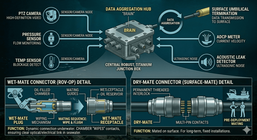
A Subsea Power Distribution Unit (PDU) receives high-voltage power from the surface and steps it down for cameras and sensors. In modern “All-Electric” subsea systems, data processing may occur locally. Edge computing within a subsea housing can compress 4K video streams or run AI algorithms for leak detection, reducing bandwidth requirements for the subsea to surface communication link.
Communication Links — How Subsea Systems Connect to the Surface
Successfully moving data from the seafloor to the surface is a significant engineering challenge, as radio waves are rapidly absorbed by saltwater. Engineers employ specialised methods to establish a reliable subsea communication link.
Method 1: Fibre Optic Umbilical Cable
For permanent installations demanding high bandwidth and low latency, the fibre optic umbilical is the preferred solution. This “lifeline” directly connects subsea assets to a surface platform or shore facility.
How it Works: Electrical or acoustic signals from sensors are converted into optical pulses, which travel through glass fibres within the umbilical. Minimal attenuation in high-quality fibre allows data transmission over dozens of kilometres without signal boosters.
Cable Construction: A subsea umbilical is a composite engineering marvel, typically consisting of:
- Fibre Optic Cores: Single-mode or multi-mode fibres for high-speed data transmission.
- Copper Conductors: To deliver high-voltage electrical power to subsea equipment.
- Steel Armour Wire: Multiple layers of galvanised steel provide tensile strength and protection against mechanical damage from anchors or fishing gear.
- Polyethene Jacket: An outer layer offering a final barrier against corrosive seawater and biological attack.
Advantages and Limitations: The primary advantage is capacity; fibre optics supports multiple 4K underwater CCTV system streams and thousands of sensor feeds simultaneously. Limitations include high cost and physical vulnerability. This method is ideal for permanent oil and gas fields or large-scale offshore wind farms.
Method 2: Acoustic Communication (Underwater Acoustic Modems)
When a physical cable is impractical, such as for temporary deployments or mobile assets, acoustic communication is the primary alternative. This method utilises sound waves, which propagate much further in water than electromagnetic waves.
How it Works: Underwater acoustic modems convert digital data into sound pulses, similar to early telephone modems. These pulses are transmitted through the water and received by a hydrophone on the surface or another subsea vehicle. Modern modems use advanced modulation techniques like OFDM to enhance data rates and reliability.
Frequency and Data Rates:
- Low Frequency (10–20 kHz): Used for long-range communication (up to 10 km) but offers very low data rates (a few hundred bits per second).
- High Frequency (50–100+ kHz): Allows for higher data rates (up to several kilobits per second) but is limited to short ranges, typically under 1 km.
USBL Positioning: Acoustic links are also integral for positioning. Ultra-Short Baseline (USBL) systems use an acoustic transceiver on a vessel to calculate the exact 3D coordinates of a subsea target by measuring the time-of-flight and phase difference of the acoustic signal.
Method 3: Electromagnetic/RF Communication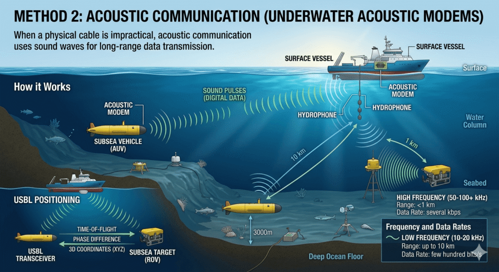
While radio frequency (RF) signals are generally ineffective underwater, they find niche applications in very short-range scenarios. High-frequency RF can travel a few meters through water, sufficient for “wireless” data harvesting from a sensor by an ROV or for inductive coupling at a docking station. This eliminates the need for physical connectors, which are prone to wear and tear in harsh subsea environments.
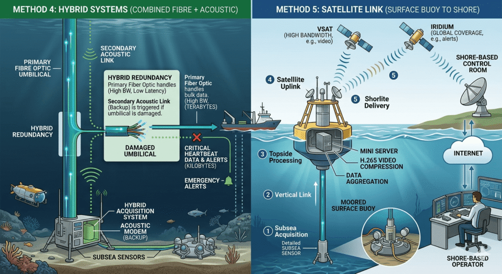
Method 4: Hybrid Systems (Combined Fibre + Acoustic)
Modern offshore monitoring system designs often employ a hybrid approach for redundancy. A primary fiber optic link handles the bulk of data, while a secondary acoustic link serves as a backup. If the umbilical is damaged, the system can still transmit critical “heartbeat” data and emergency alerts via the acoustic modem, allowing operators to maintain control while repairs are planned.
Method 5: Satellite Link (Surface Buoy to Shore)
Once data reaches the surface—via a platform or moored buoy—it must be transmitted to a shore-based control room. This is where the subsea to surface communication transitions to a satellite link.
- Subsea Acquisition: Sensors capture data on the seafloor.
- Vertical Link: Data travels up the umbilical to a surface buoy.
- Topside Processing: A small server on the buoy compresses the data using protocols like H.265 for video.
- Satellite Uplink: Using VSAT (for high bandwidth) or Iridium (for global coverage), the buoy beams the data to a satellite.
- Shore Delivery: The satellite relays the signal to a ground station, which then routes it to the operator’s control room via the internet or a private network.
System Architecture — Complete Data Flow
To fully grasp how a subsea monitoring system functions, tracing a data packet from its generation to its appearance on a technician’s screen is illustrative.
|
Step |
Location |
Action |
|
1 |
Seafloor |
A subsea inspection system camera or sensor captures raw data (e.g., a video frame or a pressure reading). |
|
2 |
Subsea Junction Box |
The raw signal is digitised and encoded into a standard protocol like Ethernet (TCP/IP). |
|
3 |
Umbilical Cable |
The data travels as light pulses through fiber optic cores within the umbilical. |
|
4 |
Topside Hub |
The signal is received by a Master Control Station (MCS) on the platform, where it is decrypted and validated. |
|
5 |
Data Compression |
Video streams are compressed (using H.265 or similar) to optimise bandwidth for the long-distance link. |
|
6 |
Long-Haul Link |
The data is transmitted to shore via a dedicated subsea fibre backbone or a satellite VSAT link. |
|
7 |
Control Room |
The data is displayed on a SCADA system or a Video Management System (VMS) for the operators. |
|
8 |
Archiving |
The data is logged into a secure Network Video Recorder (NVR) or a cloud-based historian for future analysis. |
Engineering Insight: The transition from Step 2 to Step 3 is often the most complex. It requires “Media Converters” that can operate reliably in an oil-filled, pressure-compensated environment for 20+ years without maintenance. These devices must be qualified for extreme temperature cycles and vibration during installation.
Power Supply for Subsea Systems
Providing reliable power at great depths is a significant engineering feat. Most subsea monitoring systems are powered from the surface via the same umbilical that carries the data.
Topside Power and Transmission
Due to long distances (sometimes exceeding 50km), power is often transmitted at high voltages (e.g., 3kV to 10kV AC or DC) to minimise line losses. Upon reaching the subsea distribution unit, it is stepped down using subsea transformers or DC/DC converters to 24V or 48V DC, standard for most cameras and sensors.
Autonomous and Battery Systems
For remote sensors or AUV docking stations, batteries are the primary power source. Modern subsea batteries utilize Lithium-Ion chemistry, housed in pressure-tolerant, oil-filled enclosures. Some advanced systems explore “Subsea Power Harvesting,” using ocean currents or thermal gradients to trickle-charge batteries, enabling multi-year deployments without surface intervention.
Power Budget Calculation Example
When designing a system, engineers must calculate a strict power budget. A typical small-scale monitoring node might look like this:
- 4K Subsea Camera: 15W (active)
- LED Lighting Array: 50W (high intensity for inspection)
- Acoustic Modem: 2W (standby) / 20W (transmitting)
- Sensor Suite (Pressure/Temp/Corrosion): 10W
- Subsea Ethernet Switch: 15W
- Total Peak Load:~110W per node.
Environmental Challenges and Solutions
Operating in the subsea domain is a constant battle against the laws of physics. Every component of a subsea monitoring system must be engineered to overcome specific environmental hurdles.
Pressure Management
Hydrostatic pressure increases by approximately 1 bar for every 10 meters of depth. At 3,000 meters, the pressure is a staggering 300 bar (roughly 4,350 psi). To survive this, equipment is either:
- Atmospheric (1-Atm): Housed in thick-walled titanium or steel pressure vessels, maintaining a sea-level internal environment. This is common for complex electronics.
- Pressure-Compensated: Filled with non-conductive silicone oil and equipped with a flexible compensator (bellows or bladder) that equalises internal pressure with outside water, preventing housing collapse. This method is used for cables, connectors, and simpler electronics.
Corrosion and Material Selection
Saltwater is highly corrosive, especially with dissimilar metals (galvanic corrosion). Solutions include:
- Material Choice: Using “Super Duplex” stainless steel, Titanium Grade 5, or high-nickel alloys like Inconel for critical components.
- Cathodic Protection: Attaching sacrificial zinc or aluminium anodes to the structure. These anodes corrode first, protecting the more expensive equipment.
- Coatings: High-performance epoxy, ceramic, or PTFE coatings provide an additional barrier.
Biofouling and Visibility
Marine organisms like barnacles and algae can quickly grow on surfaces, making subsea monitoring cameras ineffective. Solutions include
- Anti-fouling: Specialised clear coatings or UV-C light emitters prevent larvae from settling on lenses.
- Mechanical Wipers: Some high-end cameras feature sapphire-tipped wipers to physically clear the port.
- Water Clarity: In turbid water, laser-gated imaging or acoustic cameras (sonar) are used to “see” through silt where traditional light-based cameras fail.
Cable Damage and Protection
Subsea cables are vulnerable to fishing trawlers, ship anchors, and marine life. To mitigate this, cables are often buried 1-2 meters below the seabed using specialised subsea “plows” or protected with articulated cast-iron pipes in high-risk areas.
Standards and Certifications
To ensure safety and reliability, subsea equipment must adhere to international standards, providing a common framework for testing and quality assurance.
- DNV (Det Norske Veritas): Standards like DNV-RP-E101 provide guidelines for the qualification and recertification of subsea equipment, focusing on long-term reliability.
- API (American Petroleum Institute): API 17F is the definitive standard for subsea production control systems, covering communication protocols and environmental testing.
- IEC 61892: This series of standards covers electrical installations on offshore units, ensuring safe use in hazardous marine environments.
- NORSOK Standards: Developed by the Norwegian petroleum industry, these standards (e.g., U-001) define requirements for subsea structures and systems, widely used in the North Sea.
- IP68/IP69K: While common in many industries, in a subsea context, these ratings are a starting point. IP68 denotes continuous immersion, while IP69K adds protection against high-pressure, high-temperature washdowns.
Real-World Applications
The versatility of modern underwater surveillance systems allows deployment across various sectors:
- Oil & Gas Pipeline Monitoring: Detecting “spans” (seabed erosion under a pipe) and identifying leaks using thermal imaging and acoustic sensors.
- Offshore Wind Farm Inspection: Monitoring “J-tubes” where power cables enter turbine foundations and checking for scour (erosion) around the base using high-resolution sonar.
- Port and Harbour Security: Deploying permanent sonar and camera arrays to detect divers or Unmanned Underwater Vehicles (UUVs) approaching critical infrastructure like LNG terminals.
- Aquaculture: Using 4K cameras and oxygen sensors to monitor fish behaviour and water quality in large-scale offshore fish farms, reducing the need for human divers and improving yields.
- Scientific Research: Long-term observatories like the NEPTUNE network use subsea monitoring to study tectonic plate movements and deep-sea ecosystems in real-time.
- Subsea Cable Route Monitoring: Ensuring the integrity of global telecommunication cables against accidental damage or sabotage.
How to Design a Subsea Monitoring System (Step-by-Step Guide)
Designing a subsea system is a multi-disciplinary effort. A structured process ensures no critical factor is overlooked.
Step 1: Define Monitoring Requirements. Identify the primary goal (e.g., leak detection,
valve monitoring, security). Define depth, area of coverage, and required resolution.
Step 2: Select Camera and Sensor Types. Choose between fixed and PTZ cameras. Select sensors based on physical parameters (e.g., pressure, vibration, chemical traces). Ensure all components have the correct depth rating.
Step 3: Determine Communication Method. For real-time 4K video, fibre optics is mandatory. For occasional sensor readings from remote sites, acoustic modems may be more cost-effective. Factor in the distance to the nearest surface hub.
Step 4: Design Power Distribution. Calculate the total power draw (power budget) and decide between umbilical-powered or battery-powered operation. Factor in voltage drops for long cable runs and select appropriate transformers.
Step 5: Select Cable/Umbilical Specifications. Specify the number of fibre cores, power conductor size, and type of armour based on seabed conditions
Step 6: Plan Installation Method Determine deployment metho
d (e.g., vessel crane, ROV). Ensure all equipment has “ROV-friendly” handles, sacrificial “docking” pins, and interfaces.
Step 7: Configure Topside Equipment Set up the Master Control Station (MCS) and ensure it interfaces with existing SCADA or industrial control systems. Plan for data storage and user access levels.
Step 8: Establish Shore Link Secure the necessary bandwidth for the shore-to-platform link (satellite or secondary subsea cable). Implement cybersecurity measures for remote access.
Step 9: Testing and Commissioning Perform Factory Acceptance Testing (FAT) in a pressure tank to simulate the target depth. Once installed, conduct a Site Integration Test (SIT) to verify the full data and power path.
Step 10: Maintenance Planning Schedule regular ROV fly-bys for biofouling and anode depletion checks. Establish a plan for component replacement using wet-mate connectors and maintain critical spares.
Comparison of Subsea Communication Methods
Choosing the right subsea communication link balances data requirements against cost and range.
|
Feature |
Fiber Optic |
Acoustic |
RF / EM |
Hybrid |
|
Data Rate |
Very High (Gbps) |
Low (bps to kbps) |
Moderate (Mbps) |
High (Gbps + Backup) |
|
Range |
Long (100km+) |
Moderate (up to 10km) |
Very Short (<5m) |
Long |
|
Latency |
Extremely Low |
High (speed of sound) |
Low |
Low |
|
Cost |
High (Installation) |
Moderate |
Low |
Very High |
|
Best Use Case |
Permanent Assets |
Remote Sensors |
Docking / Harvesting |
Critical Infrastructure |
|
Limitations |
Physical Vulnerability |
Noise Interference |
Range |
Complexity |
Future Trends in Subsea Monitoring
The next decade will transform underwater interaction, driven by key technological shifts:
AI Powerd
Subsea processors will utilise machine learning to detect leaks or structural cracks, sending alerts only when anomalies are identified
Digital Twins:
-
- Real-time data from subsea sensors will feed into 3D digital models, allowing engineers to simulate “what-if” scenarios and predict failures using historical data and physics-based models.<li>
Subsea 5G:
- High-frequency blue-green lasers (Optical Wireless Communication) will enable 5G-like speeds over short distances (up to 100m) between AUVs and subsea docking stations.
- Resident AUVs:
- Autonomous vehicles living permanently on the seafloor, charging at subsea stations and performing routine inspections without surface vessel support, drastically reducing operational costs.
- Quantum Communication:
- Research into underwater quantum key distribution (QKD) aims to provide unhackable communication links for sensitive defence and high-value industrial monitoring.
FAQ Section
What is the maximum depth for subsea CCTV cameras?
Standard professional subsea cameras are typically rated for 3,000 meters; specialised systems for deep-ocean trenches can reach 11,000 meters using thick titanium housings and sapphire ports.
How far can acoustic communication work underwater?
In ideal conditions, low-frequency acoustic signals can travel up to 10–15 kilometres.
What is the difference between ROV and AUV?
An ROV (Remotely Operated Vehicle) is tethered to a ship and human-piloted. An AUV (Autonomous Underwater Vehicle) is untethered, battery-powered, and follows a pre-programmed mission using onboard AI and navigation sensors.
How is data transmitted from underwater to the surface?
The most common & high-speed methods are fibre optic umbilical cables or acoustic modems for wireless, low-speed transmission. Satellite links then bridge the gap from the surface platform to shore.
What type of cable is used for subsea communication?
Subsea communication typically uses armoured fibre optic cables, including glass fibres for data, copper wires for power, and multiple layers of steel wire armour for environmental and mechanical protection.
How long do subsea monitoring systems last?
Systems designed for the offshore industry are typically engineered for a “design life” of 20 to 25 years, requiring minimal maintenance through corrosion-resistant materials, redundant electronics, and wet-mateable connectors.
Conclusion
The evolution of the subsea monitoring system has transformed the ocean’s opaque depths into a transparent and manageable workspace. By integrating high-definition imaging, sophisticated sensors, and resilient communication links, offshore operators now manage complex underwater assets with the same precision as those on land. As we move toward autonomous “resident” vehicles and AI-driven analytics, the bridge between the seafloor and the surface will only grow stronger, ensuring sustainable and secure marine expansion.