Oil & Gas Field CCTV Systems: Well-Pad Monitoring & Zone 0 Certified Cameras — A Complete Technical Guide
Introduction
From my years of experience as an ELV/security systems engineer, particularly on demanding projects across the Middle East for giants like Saudi Aramco, ADNOC, and Qatar Energy, one truth stands paramount: safety and operational integrity in oil and gas are non-negotiable. This principle extends profoundly to our approach to CCTV systems. CCTV in the oil and gas sector is a critical tool for safety, leak detection, process monitoring, and ensuring stringent regulatory compliance. It’s the eyes and ears in environments where human presence is often restricted or hazardous.
The unique, and indeed most challenging, aspect of deploying CCTV in these environments is the omnipresent risk of explosive atmospheres. Hydrocarbons, flammable gases, and combustible dusts are inherent to oil and gas operations, transforming seemingly innocuous electrical equipment into potential ignition sources. This necessitates the use of specially designed and certified equipment – a concept often misunderstood or underestimated by those new to the industry.
The consequences of deploying non-certified equipment in hazardous areas are catastrophic. Beyond the immediate and horrific risk of an explosion, which can lead to loss of life, severe injuries, and immense environmental damage, there are significant regulatory and financial repercussions. Project shutdowns, hefty fines, and irreparable damage to a company’s reputation are very real outcomes. Major operators globally, including Shell, BP, and our regional stalwarts like Saudi Aramco and ADNOC, have stringent mandates for hazardous area CCTV, making compliance not just a best practice, but a fundamental requirement for project approval and operation.
This guide delves deep into the technical intricacies of designing, selecting, and implementing CCTV systems for oil and gas wellpads, with a particular focus on the most demanding classification: Zone 0 certified cameras. We will navigate the complexities of hazardous area classification, explore various explosion protection methods, and provide a step-by-step approach to system design, drawing on real-world insights from the field.
What is Hazardous Area Classification?
Understanding hazardous area classification is the bedrock of any safe and compliant electrical installation in the oil and gas industry. It’s a systematic method to identify and categorise locations where flammable gases, vapours, mists, or combustible dusts are present in quantities sufficient to create an explosive mixture. The primary goal is to prevent ignition by ensuring that electrical equipment, including CCTV cameras, is designed and installed to minimize the risk of sparking or overheating.
IEC/ATEX Zone System (Used in the Middle East, Europe, and most of the world):
The International Electrotechnical Commission (IEC) and the ATEX directives (from the French “ATmosphères EXplosibles”) provide a globally recognized system for classifying hazardous areas. This system categorizes locations based on the frequency and duration of the presence of an explosive atmosphere. As an engineer working in the Middle East, this is the system you will encounter almost exclusively.
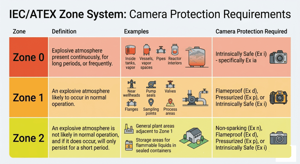
•Zone 0: This is the most critical classification. An explosive gas atmosphere is present continuously, for long periods, or frequently. Think inside process vessels, storage tanks, or pipelines where flammable substances are always present. Any equipment in Zone 0 must be designed to be incapable of causing ignition even in the event of two independent faults.
•Zone 1: An explosive gas atmosphere is likely to occur in normal operation. This includes areas around wellheads, pump seals, valves, flanges, and sampling points where leaks are possible during routine operations. Equipment here must be designed to prevent ignition during normal operation and in the event of a single foreseeable fault.
•Zone 2: An explosive gas atmosphere is not likely to occur in normal operation, and if it does occur, it will only persist for a short period. These are typically general plant areas adjacent to Zone 1 locations, where an explosive atmosphere might only arise under abnormal conditions, such as a major process upset. Equipment here must prevent ignition during normal operation.
NEC/NFC Division System (Used in North America):
While less common in the Middle East, it’s important to be aware of the National Electrical Code (NEC) and National Fire Code (NFC) Division system used predominantly in North America. This system uses “Classes” for the type of hazardous material and “Divisions” for the likelihood of its presence:
•Division 1: Roughly equivalent to a combination of Zone 0 and Zone 1. It describes locations where ignitable concentrations of flammable gases, vapors, or liquids can exist under normal operating conditions, or where they are frequently present due to maintenance or leakage.
•Division 2: Roughly equivalent to Zone 2. It describes locations where ignitable concentrations are normally prevented by ventilation, or exist only under abnormal conditions.
Gas Groups:
Beyond the zones, hazardous areas are further classified by Gas Groups, which categorize flammable gases and vapors based on their ignition energy and flame propagation characteristics. This is crucial for selecting equipment that can safely contain or prevent an explosion specific to the gas present.
•Group IIA: Propane, methane, natural gas. These have the highest ignition energy and slowest flame propagation. (e.g., typical refinery gases)
•Group IIB: Ethylene, town gas. These have lower ignition energy and faster flame propagation than Group IIA. (e.g., petrochemical plants)
•Group IIC: Hydrogen, acetylene, carbon disulfide. These are the most dangerous, with the lowest ignition energy and fastest flame propagation. Equipment certified for Group IIC can be used in Group IIA and IIB areas, but not vice-versa.
T-Class (Temperature Classification):
Finally, Temperature Classification (T-Class) specifies the maximum surface temperature that equipment can reach. This is vital to ensure that the equipment’s surface temperature, under any operating condition, does not exceed the auto-ignition temperature of the flammable gas or vapor present in the atmosphere. The classes range from T1 (450°C) to T6 (85°C). For instance, if a gas has an auto-ignition temperature of 120°C, equipment with a T4 (135°C) rating would be unsafe, and a T5 (100°C) or T6 (85°C) rating would be required.
Types of Explosion-Proof Camera Protection Methods
Selecting the right camera for a hazardous area isn’t just about its imaging capabilities; it’s fundamentally about its explosion protection method. These methods are meticulously designed and certified to prevent the camera from becoming an ignition source. As an engineer, understanding these distinctions is paramount.
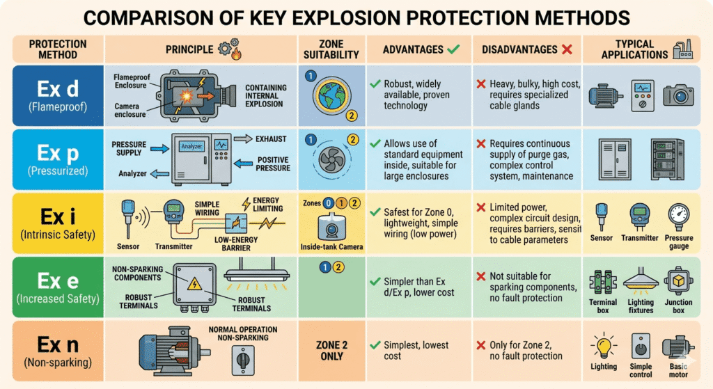
•Ex d — Flameproof Enclosure: This is perhaps the most common and robust protection method. The camera and its electrical components are housed within an enclosure strong enough to contain an internal explosion and prevent the transmission of flames or hot gases to the surrounding explosive atmosphere. The enclosure itself is not gas-tight; gases can enter. However, the gaps in the enclosure (e.g., at cable entries or between mating surfaces) are precisely engineered to cool any escaping hot gases below the auto-ignition temperature of the external atmosphere. These enclosures are typically heavy, made of thick stainless steel or cast aluminum, and are often used for high-power devices in Zone 1 and Zone 2 areas.
•Ex p — Pressurized/Purged Enclosure: In this method, the enclosure containing the camera is maintained at a pressure higher than the surrounding hazardous atmosphere using a protective gas (usually instrument air or inert gas like nitrogen). This positive pressure prevents the ingress of flammable gases or dusts. A control system monitors the pressure, and if it drops below a safe level, power to the camera is automatically cut off. There are different types (Ex px, Ex py, Ex pz) depending on the level of protection and the zone. Ex p is often used for larger equipment or complex assemblies that cannot be easily made flameproof, and is suitable for Zone 1 and Zone 2.
•Ex i — Intrinsic Safety: This is the only protection method suitable for Zone 0. Intrinsically safe equipment is designed such that the electrical energy (current and voltage) and stored energy (capacitance and inductance) within the circuit are always kept below the level required to ignite the most easily ignitable explosive mixture. This is achieved through the use of Zener barriers or galvanic isolators, which limit the energy supplied to the hazardous area device. The philosophy here is to prevent ignition by making sparks or hot surfaces impossible, rather than containing an explosion. Ex ia is the highest level of intrinsic safety, allowing for two faults to occur without causing ignition, making it suitable for Zone 0. Ex ib allows for one fault, suitable for Zone 1, and Ex ic for normal operation, suitable for Zone 2.
•Ex e — Increased Safety: This method focuses on preventing sparks and hot surfaces in electrical equipment that does not produce sparks or hot surfaces in normal operation. It involves enhanced insulation, increased creepage and clearance distances, and robust mechanical construction to prevent arcs, sparks, or excessive temperatures. Ex e is typically applied to terminal boxes, junction boxes, and certain types of motors, and is suitable for Zone 1 and Zone 2. It is not suitable for equipment that inherently produces sparks or heat, like camera electronics.
•Ex n — Non-sparking: This is the simplest protection method, suitable only for Zone 2. It applies to electrical equipment that, in normal operation, is not capable of causing ignition. This includes equipment where sparking contacts are enclosed or where hot surfaces are limited. It does not protect against faults, only against ignition during normal, fault-free operation. Ex n is further subdivided into Ex nA (non-sparking apparatus), Ex nC (enclosed break apparatus), Ex nL (energy-limited apparatus), and Ex nR (restricted breathing enclosures).
Zone 0 Certified Cameras — What Makes Them Special?
When we talk about Zone 0 certified cameras, we are entering the pinnacle of hazardous area protection. As established, Zone 0 is where an explosive atmosphere is present continuously or for long periods. This demands the absolute highest level of safety, and for electrical equipment, this almost exclusively means Intrinsic Safety (Ex ia). My experience dictates that anything less is simply unacceptable and a direct violation of safety protocols.
True Zone 0 cameras are fundamentally different from their Zone 1 or Zone 2 counterparts. They are not merely housed in a heavy, explosion-proof enclosure (Ex d); instead, their internal circuitry is designed to be incapable of generating enough energy to cause an ignition, even under fault conditions. This is achieved through:
1.Energy Limitation: All electrical parameters (voltage, current, power) are severely restricted to levels below the minimum ignition energy (MIE) of the most sensitive gas group (IIC, e.g., hydrogen). This means that any spark generated, or any hot surface created, will not have enough energy to ignite the surrounding atmosphere.
2.Galvanic Isolation/Zener Barriers: These devices are installed between the safe area power supply/data network and the camera in the hazardous area. They prevent unsafe levels of energy from entering the hazardous zone, effectively isolating the intrinsically safe circuit.
3.Robust Design and Component Selection: Components are chosen for their reliability and low power consumption. Circuit boards are often encapsulated to prevent accidental short circuits or component damage.
4.Fiber Optic Integration: For data transmission, fiber optic cables are often preferred for Zone 0 cameras. Fiber optics are inherently non-electrical and immune to electromagnetic interference, making them ideal for transmitting video signals without introducing an ignition risk. The camera itself will still require an intrinsically safe power supply, but the data link is intrinsically safe by nature.
Zone 1 Cameras — The Workhorses of Oil & Gas CCTV
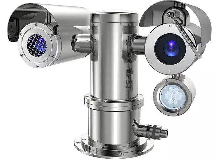
While Zone 0 cameras address the most extreme risks, Zone 1 cameras are arguably the workhorses of oil and gas CCTV systems. These are the cameras you’ll find most frequently deployed around wellheads, manifolds, processing units, and other areas where an explosive atmosphere is likely to occur during normal operation. The predominant protection method for Zone 1 CCTV is Ex d flameproof enclosures.
An Ex d camera is a marvel of engineering. It’s designed to withstand an internal explosion without propagating it to the outside. This means the enclosure must be incredibly robust, typically constructed from heavy-duty stainless steel (often 316L for corrosion resistance in harsh environments) or specialised aluminium alloys. The joints, such as threaded entries for conduits and mating surfaces, are machined to extremely tight tolerances, creating a “flame path” that cools any escaping hot gases below the ignition temperature of the external atmosphere. This design philosophy is critical for ensuring safety in Zone 1.
Key Features and Considerations for Zone 1 Ex d Cameras:
•Material: 316L Stainless Steel is preferred for its corrosion resistance, especially in offshore or coastal environments. Aluminum is lighter but may not be suitable for all corrosive atmospheres.
•Certification: Look for full ATEX and IECEx certification for Zone 1, including the correct gas group (e.g., IIB or IIC) and temperature class (T-Class).
•Environmental Ratings: IP66/IP67/IP68 for dust and water ingress protection, NEMA 4X for corrosion resistance.
•Optics: High-resolution sensors (4MP, 8MP, 4K), optical zoom, and low-light performance with IR illumination are standard requirements for clear identification and monitoring.
•Heaters/Wipers: Essential for extreme temperatures and to maintain visibility in dusty, rainy, or icy conditions.
•Mounting: Robust mounting brackets designed for heavy enclosures and capable of withstanding vibrations and high winds.
•Cable Glands: Must be certified flameproof (Ex d) and correctly installed to maintain the integrity of the enclosure.
Key Brands and Models: Many reputable CCTV manufacturers offer Ex d certified cameras for Zone 1. Some prominent names include:
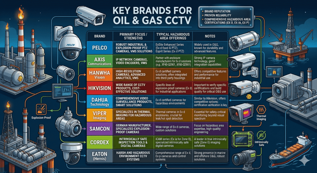
•Pelco: Known for their Esprit series, including explosion-proof PTZ (Pan-Tilt-Zoom) cameras that are widely used in industrial applications. Their ExSite Enhanced series offers high-resolution fixed and PTZ options.
•Axis Communications: Offers a range of explosion-protected cameras, often partnering with specialized enclosure manufacturers to integrate their camera modules into certified Ex d housings. Their XF40-Q2901 and XF60-Q2901 are examples of fixed thermal and visual cameras in Ex d enclosures.
•Hanwha Vision (formerly Samsung Techwin): Provides robust explosion-proof camera solutions, often integrated into third-party certified housings, offering high-resolution and advanced analytics capabilities.
•Hikvision & Dahua: While primarily known for their mainstream CCTV products, both offer specific lines of explosion-proof cameras for industrial applications, often at competitive price points. It’s crucial to verify their certifications and build quality for critical oil and gas deployments.
•Viper Imaging: Specializes in thermal imaging cameras for hazardous areas, often in Ex d enclosures, crucial for leak detection and temperature monitoring.
•Samcon: A German manufacturer specializing in explosion-proof and industrial cameras, offering a wide range of Ex d solutions.
•Spectrum: Another specialized provider of hazardous area camera systems.
When selecting a Zone 1 camera, it’s not just about the brand; it’s about the specific model’s certification, its build quality, and its suitability for the exact environmental and hazardous area conditions of the wellpad.
Wellpad Monitoring System Design
Designing a CCTV system for an oil and gas wellpad is a meticulous process that demands a deep understanding of both surveillance technology and hazardous area regulations. As an engineer who has overseen numerous such deployments, Here’s a step-by-step guide:
Step 1: Understand the Wellpad Layout and Operational Requirements
Before even thinking about cameras, you must thoroughly understand the wellpad. This involves:
•Site Visit/P&IDs Review: Walk the site (if safe) or meticulously review Process & instrumentation diagrams (P&IDs), plot plans, and 3D models. Identify all critical assets: wellheads, manifolds, separators, storage tanks, flare stacks, chemical injection skids, control rooms, access points, and perimeter boundaries.
•Operational Flows: Understand the normal operational procedures, maintenance routines, and potential upset conditions. What processes need to be monitored? Where are potential leak points? What are the security vulnerabilities?
•Stakeholder Requirements: Interview operations, safety, security, and environmental teams. What are their specific monitoring needs? What events do they need to detect or verify?
Step 2: Determine Hazardous Area Classification
This is the most critical step. Based on the wellpad layout and the types of hydrocarbons present, work with process and safety engineers to obtain the official hazardous area classification drawings. These drawings will clearly delineate Zone 0, Zone 1, and Zone 2 boundaries, along with the relevant gas groups and temperature classes for each area. Never assume; always work with certified documentation.
Step 3: Select Camera Types for Each Zone
With the hazardous area classifications firmly established, you can now select the appropriate camera protection method for each location:
•Zone 0: Ex ia Intrinsically Safe cameras (often fiber optic for data).
•Zone 1: Predominantly Ex d Flameproof cameras. Ex p Pressurized cameras can also be considered for specific applications.
•Zone 2: Ex d Flameproof, Ex p Pressurized, or Ex n Non-sparking cameras. Ex n offers a lower cost but with reduced protection levels.
•Safe Area: Standard industrial-grade cameras (e.g., IP66/IK10 rated) can be used in control rooms, administrative buildings, or clearly defined non-hazardous zones.
Step 4: Choose Camera Specifications
Once the protection method is determined, focus on the camera’s performance:
•Resolution: 4MP, 8MP (4K), or even higher for critical areas requiring detailed inspection or digital zoom capabilities.
•Lens Type: Fixed lens for wide overview, varifocal for adjustable field of view, or PTZ (Pan-Tilt-Zoom) for dynamic monitoring and event investigation. PTZ cameras are invaluable for covering large areas with fewer cameras.
•Low-Light/IR Performance: Essential for 24/7 monitoring. Built-in IR illuminators or external IR floodlights are often required.
•Thermal Imaging: Crucial for leak detection (gas leaks, hot spots), flare monitoring, and early fire detection, especially in areas with poor visibility or where traditional cameras struggle.
•Analytics: Video analytics (e.g., motion detection, intrusion detection, object tracking, line crossing) can significantly enhance situational awareness and reduce operator fatigue.
•Environmental: Ensure IP rating (IP66/67/68), NEMA rating (e.g., NEMA 4X for corrosion), and operating temperature range are suitable for the wellpad’s climate.
Step 5: Design the Network Architecture
The network infrastructure for wellpad CCTV is as critical as the cameras themselves. Fiber optic cabling is almost always the preferred choice for its immunity to EMI/RFI, long transmission distances, and inherent safety (no electrical signals). Ethernet over fiber media converters will be required at each camera location and at the control room.
•Topology: Ring topology (e.g., using industrial Ethernet switches with redundant fiber links) is highly recommended for resilience. Star or daisy-chain topologies are less robust.
•Bandwidth: Calculate the required bandwidth based on the number of cameras, resolution, frame rate, and compression (H.264, H.265). Ensure sufficient bandwidth for live viewing, recording, and analytics.
•Cybersecurity: Implement robust cybersecurity measures, including VLANs, firewalls, strong authentication, and encryption for video streams.
Step 6: Power Supply Design
Powering hazardous area cameras requires careful planning:
•Safe Area Power: Power supplies for hazardous area cameras must originate from a safe area. For Ex ia cameras, intrinsically safe power supplies (barriers) are mandatory.
•Voltage: Typically 24V AC/DC or 12V DC for cameras. Ensure voltage drop calculations are performed for long cable runs.
•UPS/Battery Backup: Uninterruptible Power Supplies (UPS) with sufficient battery backup are essential to maintain surveillance during power outages.
•Earthing/Grounding: Proper earthing and bonding are critical for safety and to prevent electrical interference.
Step 7: Cable and Conduit Selection
Cable and conduit selection must comply with hazardous area standards and local regulations:
•Cable Type: Armored fiber optic cables for data, and armored power cables (e.g., SWA – Steel Wire Armored) for power, suitable for direct burial or tray installation.
•Conduit/Cable Glands: All conduits and cable glands entering Ex d or Ex p enclosures must be certified for hazardous areas and correctly installed. For Ex d, flameproof glands are essential. For Ex i, specific intrinsically safe cable routing and segregation rules apply.
•Cable Routing: Cables must be routed away from potential damage, heat sources, and other interference. Cable trays, trenches, or direct burial are common methods.
Step 8: Installation and Commissioning
Installation must be carried out by certified personnel (e.g., CompEx certified technicians) strictly following design drawings and manufacturer instructions.
•Mounting: Cameras must be securely mounted on poles or structures designed to withstand environmental loads (wind, vibration) and provide optimal fields of view.
•Focus and Alignment: Proper focus, iris adjustment, and alignment are crucial for image quality. For PTZ cameras, pre-set tours and home positions should be configured.
•Network Configuration: IP addressing, network settings, and VMS (Video Management System) integration must be meticulously configured.
•Loop Checks/Testing: Thorough loop checks, functional testing, and hazardous area inspection (e.g., checking flame paths, gland tightness) are mandatory before energizing the system.
Step 9: Integration with Safety Systems (DCS, F&G, ESD, SCADA)
Modern wellpad CCTV systems are not standalone; they are integral components of the overall safety and control architecture. Integration with other critical systems enhances situational awareness and response capabilities:
•DCS (Distributed Control System): Video feeds can be displayed on DCS operator workstations, allowing process operators to visually verify alarms, monitor equipment, and observe critical operations.
•F&G (Fire & Gas Detection System): Alarms from F&G detectors (e.g., gas leaks, flame detection) can trigger CCTV cameras to pan to the alarm location, record high-resolution video, and alert operators. Thermal cameras are particularly effective here.
•ESD (Emergency Shutdown System): In the event of an ESD activation, CCTV can provide critical visual confirmation of the incident, assist in personnel evacuation monitoring, and support post-incident investigation.
•SCADA (Supervisory Control and Data Acquisition): CCTV can provide visual context to SCADA data, allowing operators to see the physical conditions corresponding to sensor readings or control commands.
Integration typically involves industrial protocols like Modbus TCP/IP or OPC UA, or direct API integration with the VMS. It’s a complex task requiring close collaboration between CCTV, ICSS (Integrated Control and Safety Systems), and IT teams.
Step 10: Maintenance and Inspection
Regular maintenance and inspection are vital to ensure the continued safe and reliable operation of hazardous area CCTV systems.
•Routine Checks: Daily/weekly checks for camera functionality, image quality, and network connectivity.
•Preventive Maintenance: Quarterly/bi-annual cleaning of camera lenses, inspection of cabling, glands, and enclosures for corrosion or damage. Verification of purge systems (for Ex p) and barrier integrity (for Ex i).
•Certification Audits: Periodic audits by certified hazardous area inspectors to ensure ongoing compliance with ATEX/IECEx standards.
•Software Updates: Regular updates for camera firmware and VMS software to address security vulnerabilities and improve performance.
Key Brands for Oil & Gas CCTV
Common Mistakes in Oil & Gas CCTV Projects
Having witnessed numerous projects, both successful and those fraught with challenges, I can highlight several common pitfalls that engineers and project managers often encounter in oil and gas CCTV deployments:
1.Underestimating Hazardous Area Classification: This is by far the most critical mistake. Assuming a general “explosion-proof” requirement without detailed zone, gas group, and T-class analysis leads to either over-specification (unnecessary cost) or, worse, under-specification (catastrophic safety risk). Always demand certified hazardous area drawings.
2.Ignoring Environmental Factors: The Middle East’s harsh climate (extreme heat, dust, sandstorms, corrosive atmospheres near the coast) can quickly degrade standard equipment. Failing to specify 316L stainless steel, appropriate IP/NEMA ratings, and robust cooling/heating solutions leads to premature equipment failure and high maintenance costs.
3.Poor Network Design: Treating the CCTV network as a secondary consideration. Insufficient bandwidth, lack of redundancy (no fiber ring), and inadequate cybersecurity measures result in dropped frames, video latency, and vulnerability to cyber threats. A robust, secure, and redundant network is foundational.
4.Inadequate Power Planning: Overlooking voltage drop over long distances, insufficient UPS backup, or improper earthing can lead to camera outages, poor performance, and safety hazards. Power design for hazardous areas is complex and requires specialist input.
5.Lack of Integration Planning: Deploying CCTV as a standalone system misses a huge opportunity for enhanced safety and operational efficiency. Failing to integrate with DCS, F&G, and ESD systems means operators lose critical visual context during alarms and emergencies.
6.Cutting Corners on Installation & Certification: Using non-certified personnel for hazardous area wiring, improper cable gland installation, or bypassing required inspections are recipes for disaster. These shortcuts invalidate certifications and create immediate ignition risks.
7.Neglecting Maintenance: Hazardous area equipment requires specialized and regular maintenance. Skipping cleaning, inspection of flame paths, or verification of intrinsic safety barriers can compromise the system’s integrity over time.
8.Focusing Solely on Cost: While budget is always a factor, prioritizing the lowest upfront cost over certified, reliable equipment and proper engineering in hazardous environments is a false economy. The cost of a single incident far outweighs any savings.
9.Poor Documentation: Inadequate “as-built” drawings, certification records, and maintenance logs make troubleshooting, future expansions, and regulatory audits incredibly difficult.
Avoiding these common mistakes requires a holistic approach, a commitment to safety standards, and a willingness to invest in proper engineering and certified equipment.
Standards and Regulations
Compliance with international and local standards is not merely a bureaucratic hurdle; it is the legal and ethical framework that ensures safety and reliability in hazardous environments. For oil and gas CCTV systems, several key standards and regulations dictate design, installation, and operation:
•IEC 60079 Series (International Electrotechnical Commission): This is the foundational international standard for electrical equipment for explosive atmospheres. It comprises numerous parts covering general requirements, equipment protection levels, constructional requirements for various protection types (Ex d, Ex i, Ex p, etc.), installation, inspection, and maintenance. It is the basis for both ATEX and IECEx certifications.
•ATEX Directives (2014/34/EU and 1999/92/EC): These are European Union directives.
•ATEX 2014/34/EU (Equipment Directive): Mandates that equipment and protective systems intended for use in potentially explosive atmospheres must be certified before being placed on the EU market. This is what manufacturers comply with to get their cameras certified.
•ATEX 1999/92/EC (Workplace Directive): Requires employers to classify hazardous areas and ensure the safe use of equipment in those areas. This is what end-users (like oil and gas operators) must comply with.
•IECEx (International Electrotechnical Commission System for Certification to Standards Relating to Equipment for Use in Explosive Atmospheres): A global certification scheme that facilitates international trade of equipment for use in hazardous areas. An IECEx certificate is widely recognized and accepted in many countries, including those in the Middle East, often simplifying the approval process compared to country-specific certifications. It ensures that equipment meets the relevant IEC standards.
•Saudi Aramco Engineering Standards (SAES): For projects within Saudi Arabia, adherence to Saudi Aramco’s comprehensive SAES documents is mandatory. Key SAES relevant to CCTV and hazardous areas include:
•SAES-T-555: Video Surveillance Systems: This standard outlines the requirements for the design, installation, testing, and maintenance of video surveillance systems, including specifics for hazardous area applications.
•SAES-B-062: Hazardous Area Classification: Provides detailed guidelines for classifying hazardous areas within Saudi Aramco facilities.
•Other relevant SAES documents cover electrical installations, cabling, and instrumentation in hazardous locations.
•ADNOC Group Standards: Similar to Saudi Aramco, ADNOC (Abu Dhabi National Oil Company) has its own set of engineering standards and specifications that must be followed for projects within the UAE.
•API RP 500/505 (American Petroleum Institute Recommended Practices): These are widely used in North America (and sometimes referenced globally) for classifying hazardous locations for electrical installations in petroleum facilities.
•API RP 500: Covers the Class/Division system.
•API RP 505: Covers the Zone system as applied to petroleum facilities.
•CompEx (Competency in Explosive Atmospheres): A global scheme that certifies the competency of personnel working in hazardous areas. It ensures that electricians, technicians, and engineers have the necessary skills to safely install, inspect, and maintain Ex equipment. Many oil and gas operators mandate CompEx certification for personnel working on their hazardous area projects.
Adhering to these standards is not just about avoiding penalties; it’s about embedding a culture of safety and engineering excellence into every aspect of an oil and gas CCTV project.
FAQ Section
Here are some frequently asked questions regarding Oil & Gas Field CCTV Systems and hazardous areas:
Q1: What is the primary difference between an explosion-proof camera and an intrinsically safe camera?
A1: An explosion-proof (Ex d) camera contains an internal explosion, preventing it from igniting the external atmosphere. An intrinsically safe (Ex i) camera prevents ignition by limiting the electrical and thermal energy within its circuits to levels too low to cause an explosion, even under fault conditions. Ex i is the only method suitable for Zone 0.
Q2: Why is fibre optic cabling preferred for hazardous area CCTV?
A2: Fibre optic cables are preferred because they are inherently non-electrical, meaning they cannot generate sparks or heat, making them intrinsically safe for data transmission. They are also immune to electromagnetic interference, crucial in industrial environments, and support long transmission distances.
Q3: Can a Zone 1 certified camera be used in a Zone 0 area?
A3: Absolutely not. A Zone 1 certified camera (typically Ex d) is designed for areas where an explosive atmosphere is likely to occur. Zone 0 requires equipment that is safe even under multiple fault conditions (Ex ia intrinsic safety). Using a Zone 1 camera in Zone 0 is a severe safety violation and extremely dangerous.
Q4: What is the significance of the T-Class rating for hazardous area cameras?
A4: The T-Class (Temperature Classification) indicates the maximum surface temperature that any part of the camera can reach under normal or fault conditions. It is crucial to ensure this temperature is always below the auto-ignition temperature of the specific flammable gas or vapour present in the hazardous area to prevent ignition.
Q5: What are the specific challenges for offshore CCTV systems compared to onshore?
A5: Yes, offshore systems face additional challenges including extreme corrosion (saltwater, humidity), high winds, constant vibration, limited space, and often more complex power and network infrastructure. This necessitates even more robust materials (e.g., 316L stainless steel), specialized mounting, and often more compact designs.
Q6: How does CCTV integrate with other safety systems on a wellpad?
A6: CCTV systems can integrate with Distributed Control Systems (DCS), Fire & Gas (F&G) detection systems, and Emergency Shutdown Systems (ESD). This allows for visual verification of alarms, automatic camera call-ups to incident locations, and provides critical visual context for operators during emergencies, enhancing overall safety and response.
Q7: What certifications should I look for when selecting a hazardous area camera?
A7: For global projects, look for ATEX (for Europe) and IECEx (international) certifications, specifying the correct Zone (e.g., Zone 1, Zone 0), Gas Group (e.g., IIB, IIC), and Temperature Class (e.g., T3, T4). For specific regions like Saudi Arabia, adherence to local standards like Saudi Aramco SAES is also mandatory.
Q8: What is the role of video analytics in wellpad monitoring?
A8: Video analytics can significantly enhance wellpad monitoring by providing automated detection of events. This includes motion detection for security, line crossing for perimeter breaches, object tracking, and even specialized analytics for detecting smoke, flames, or abnormal process conditions, reducing the reliance on constant human observation.
Conclusion
Deploying CCTV systems in oil and gas fields, particularly for wellpad monitoring and hazardous environments, is a complex yet essential task. It requires a solid understanding of hazardous area classifications, explosion protection methods, and adherence to both international and local standards. Each component, from Zone 0 intrinsically safe cameras to Zone 1 Ex d systems, plays a crucial role in safeguarding personnel and ensuring environmental compliance. Based on my experience in the Middle East, a holistic approach is vital. This includes thorough site assessments, accurate hazardous area mapping, careful selection of certified equipment, and resilient network design. Proper planning, certified installation, and ongoing maintenance are key to avoiding common pitfalls. A well-designed hazardous area CCTV system is more than just cameras; it enhances operational and safety efforts by providing critical real-time visual intelligence. Investing in the right technology and expertise is essential for the industry’s future.