No Response from lift control panel
Why lift control panel AR-401-IO-0016R have a non-response?
The precaution of replacing a controller of an elevator.
There are several possible reasons for this issue when replacing a controller for an elevator. These include:
Controller Model: Ensure that the new controller is compatible with the elevator system.
DIP Switch Setting: Verify that the DIP switches on the controller are properly configured.
Converter Model: Check if the converter model is suitable for the elevator system.
Enable/Disable Lift Control Function: Confirm whether the lift control function is enabled or disabled.
Converter Distance to Controller: Consider the distance between the converter and the controller and ensure it meets the requirements.
LED Indicator Issue of AR-401-IO-0016R: Address any problems with the LED indicators on the control panel.
701ServerSQL – Network Base Option: Check the settings and configuration of the network base option for 701ServerSQL.
Connection Base Option (With/Without Multi-door Control Panel): Determine if the connection base option is appropriate for the specific elevator system, with or without a multi-door control panel.
User Access Floor Data Download/Update: Verify that the floor data download/update process for user access is functioning correctly.
An Introduction:
In this article, we’ll help you troubleshoot problems with the lift control panel. Whether it’s a hardware or software issue, just follow these steps to solve the problem:
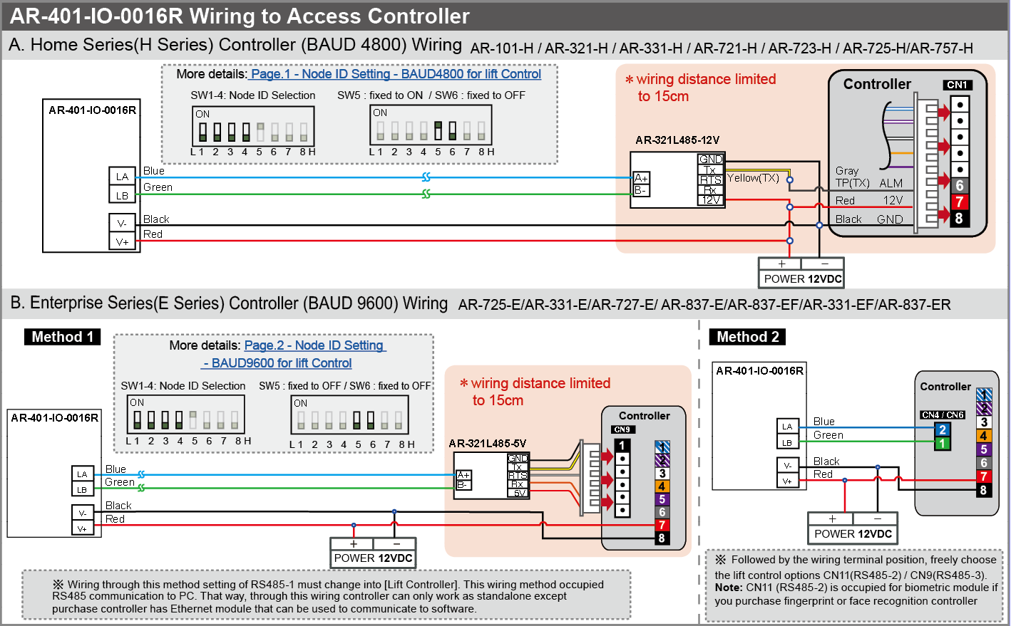
Wiring Configuration: To begin, refer to the AR-401-IO-0016R Manual for detailed instructions on how to check and configure the wiring of the lift control panel. This will ensure that all the connections are properly set up and functioning correctly.
Software Parameter Setting: Next, refer to the 701ClientSQL Manual – Chapter 11 which guides how to adjust the software parameters for the lift control panel. This step is important as it allows you to fine-tune the settings and ensure they are optimized for your specific needs.
Frequently asked questions about the hardware:
Controller Model :
When it comes to SOYAL controllers, they can be categorized into two main series: H and E. These series have some variations in terms of wiring, converters, and DIP switches.
If you’re considering replacing a controller, a common option is to substitute the AR-725E model for the AR-725H model. However, it’s important to note that their configurations are different. So, keep in mind that you’ll need to adjust accordingly when making this switch.
 DIP Switch
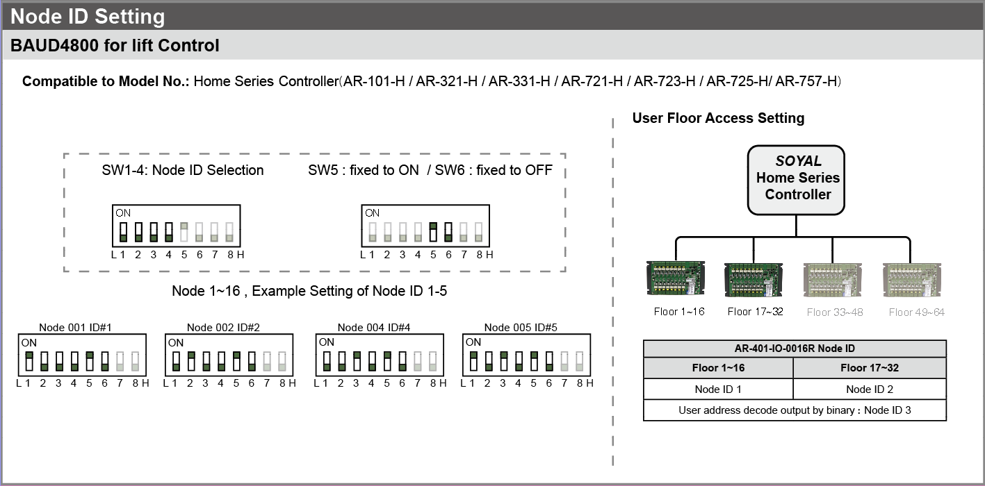
H Series:
The first control panel which controls 1-16 floors of the building, switch 1/5/8 Should be ON
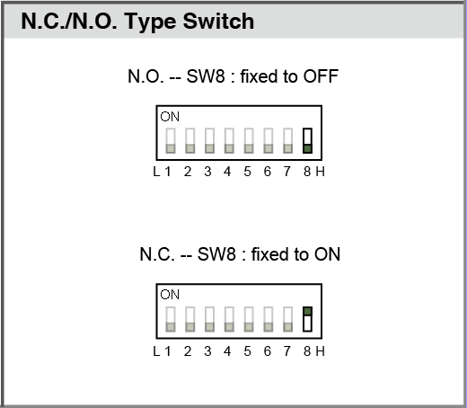
E Series:
The first control panel which controls 1-16 floors, switches 1/8 should be ON
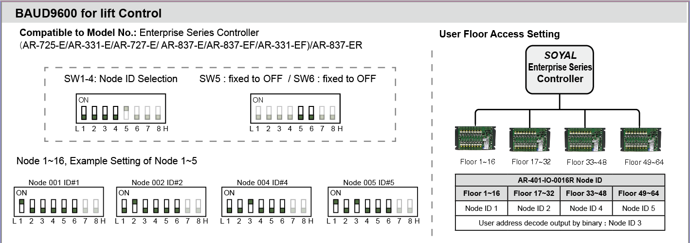
DIP switch 8:
The Model of Converter
When it comes to the controllers, there are specific requirements for each series.
The H series controller is designed to work with the AR-321L485-12V, while the E series controller is designed for the AR-321L485-5V. It’s important to note that substituting one for the other is not allowed.
Enabling or disabling the lift control function: For the H series controller, you need to use a keypad command to enable this function. To do so, enter the program mode and input 24*066#. By default, the value 064 is enabled, which means that the sum value should be 002+064=066.This process is specific to the H series controller and allows you to control the lift function through the keypad

The E series controller
comes with the lift control function already enabled by default. So, when you’re using a new E series controller, you don’t need to go through the process of setting parameters for the lift control function.
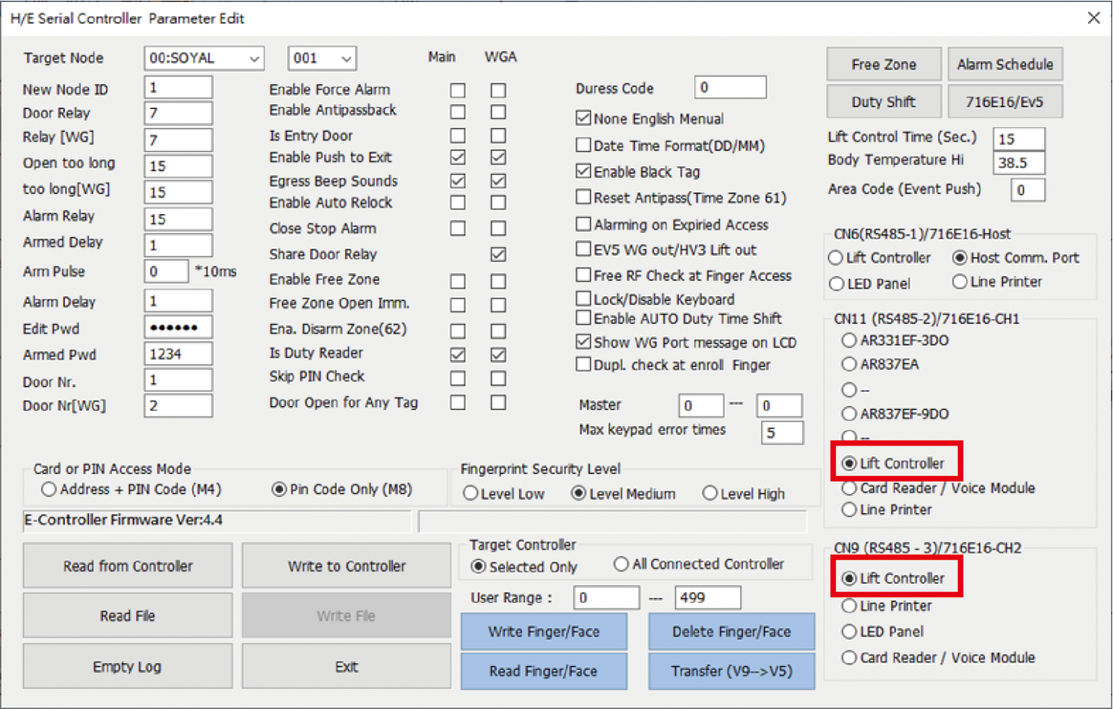
To ensure that the lift control function is properly configured, you can use the 701ServerSQL software. By accessing this software, you can read the controller parameters and verify that CN9 and CN11 have been set to enable the lift control function.
This step allows you to confirm that the necessary settings are in place for the lift control function to work as intended with the E-series controller.
A controller with an LCD screen is also available to confirm the settings on the controller,
CN9: Enter program mode > 5. Tools > 0. UART Port CN9 > Lift 9600
CN11: Enter program mode > 5. Tools > 5. Ext. Comm CN11 > Lift
Configuration Distance
The distance between the converter and controller is restricted below 15cm, or the communication will be abnormal.
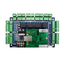
The LED indicator issue of AR-401-IO-0016R
Under normal circumstances, the lift control panel will only illuminate the LED indicator for the power supply. This indicates that everything is functioning correctly.
However, if you notice that the Tx/Rx LED indicator is also lit up, it suggests that there may be a problem with one of the devices. This is an indication that communication between devices might be disrupted or that there could be a malfunction in one of the components.
it is important to investigate and troubleshoot the issue further to identify the specific device that is causing the problem and take appropriate measures to address it.
remember that before unplugging the 321L485-5V/12V converter, it should be de-energized. This means that power should be disconnected from the converter before you unplug it. This precaution is necessary to prevent any potential damage to the device. So, always make sure to turn off the power before unplugging the 321L485-5V/12V converter to keep it safe and in good working condition.
| Tx lighted up | The malfunction of the AR-401-IO-0016R panel |
| Rx lighted up | The malfunction of 321L485-5V/12V converter |
Frequently asked questions about software
701ServerSQL – LAN(Network-TCP-IP) Base Option
If you substitute the controller model AR-725E for AR-725H, it is required to modify the 701ServerSQL LAN(Network) base option from 3K 321/331/725/888H to 327E/3xxE…/716Ev5.
701ServerSQL LAN Base Table

Connection Based Option (With / Without Multi-door Control Panel)
(1) Directly or Via Network switch connect the controller to the PC (Without multi-door control panel):
Step1. Select the target area of the controller and “Download directly to selected controllers listed below”.
Step2. Select the Node ID of the controller.
Step3. Execute the download and read function.

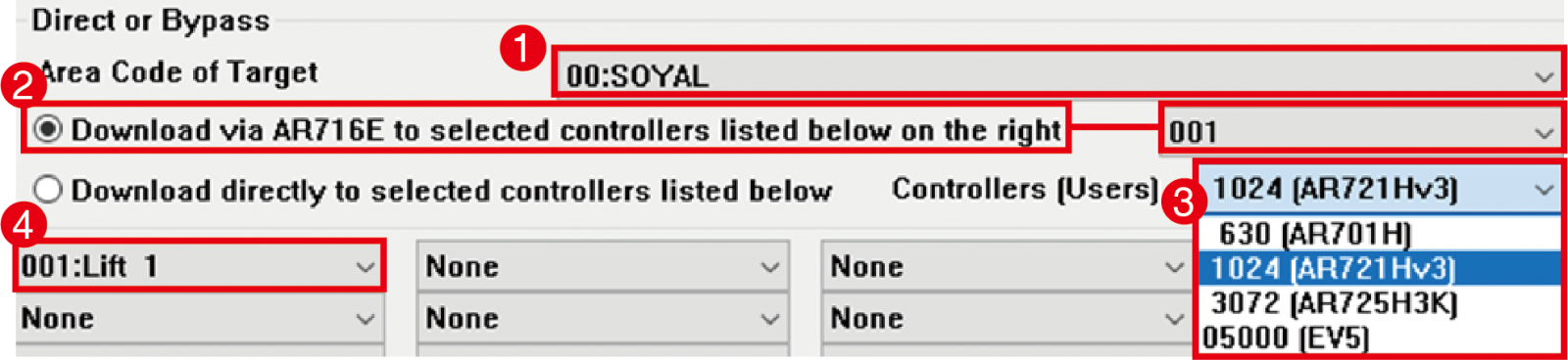
If Controllers connect via the Multi-door Control Panel: follow the following Steps:
Step1. Select target area
Step2. Select “Download via AR716E to selected controllers listed below on the right” and the Node ID of Multi-door Control Panel
Step3. Select controller model (1024-H Series / 3072-725H / 05000-E Series)
Step4. Select the Node ID of the controller.
Step5. Execute the download and read function.
The following table for floor control determination and identification:
One common issue that customers may come across when using the centralized architecture of dual-floor mode is when the floor control data is only downloaded to the second-floor controller. This can lead to situations where card verification is successful, but the relays do not respond as expected.
To address this problem, it is important to resolve the issue by re-downloading the floor control data to the multi-door controller. This ensures that the correct data is properly distributed and synchronized across all the necessary controllers. By doing so, you will be able to rectify the situation and ensure that the relays respond appropriately, providing smooth and reliable operation in the dual-floor mode.

User Access Floor Data Download / Update
The original data of the user access floor had been saved in the controller after the last edit, so it is available to download relevant data from the controller. If your controller is broken and the data hasn’t been backed up before, then it is required to rebuild all user access floor data.
Step1. Make sure the old controller is online.

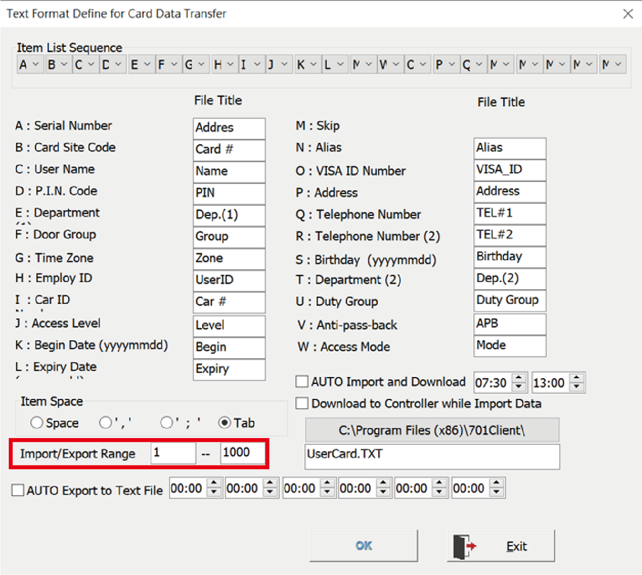
Step2. Confirm the import/export user range
701ClientSQL > Tools > Import / Export Format of Card
Step3. Select 8. User cards edit.

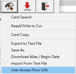
Step4. Select tools box > floor edit
Step5. Select the connection function
Step6. Assign the controller Node ID
Step7. Input user range and press “Read Range from 1st Node”.
Step8. Select a random user in range to confirm the data has been read correctly, then select “Save to Text”.

Step9. Connect the new controller.

Step10. Select the connection function again.
Step11. Press “Read from Text” and select the file.
Step12. Assign the user range and press “Write Range”.

Step13. Finally, close the window of access floor edit, then open it again and use “Read One from 1st Node” or “Read Range from 1st Node” to confirm the data has been updated correctly.