
FIRE ALARM DESIGN FOR HIGH-RISE BUILDINGS
A Complete Technical Guide — BS 5839 | NFPA 72 | EN 54 | Saudi Civil Defence | GCC Region
High-rise buildings present some of the most demanding fire alarm engineering challenges in the built environment. Evacuation of thousands of occupants across 20, 40, or even 80 floors cannot happen simultaneously — and yet every second counts when smoke is present. Getting the fire alarm design right is not just a compliance exercise: it is, quite literally, a life-safety engineering decision.
This article covers everything a fire alarm engineer, ELV consultant, or M&E project manager needs to know — from system architecture and detector selection to zoning logic, voice evacuation, BMS integration, and compliance with BS 5839-1, NFPA 72, and the Saudi Civil Defence requirements prevalent across the GCC.
This guide targets engineers and technical professionals specifying or installing fire alarm systems in buildings above 30 metres (approximately 10 floors or more). The principles also apply to complex mid-rise facilities such as hospitals, hotels, and mixed-use towers.
1. What Makes High-Rise Fire Alarm Design Different?
A standard fire alarm design — where a single sounder activation evacuates the whole building — falls apart in a high-rise context. The challenges are structural, logistical, and regulatory:
- Stack effect: Hot smoke rises faster in tall shafts (stairwells, lift cores), spreading to floors far from the source
- Simultaneous total evacuation is physically impossible — stairwells cannot handle full occupant load
- Extended detection-to-evacuation timelines require phased or progressive evacuation strategies
- Long cable runs between floors create voltage drop and loop resistance issues
- Higher background noise levels require carefully calibrated sounder dB outputs
- Complex occupancy mix (retail, residential, office, plant rooms) demands zone differentiation
- Integration with lifts (firefighter lifts), pressurisation systems, BMS, and suppression
KEY PRINCIPLE: In a high-rise, the fire alarm system is not just a detection and notification tool — it is the backbone of the entire life-safety strategy.
2. Governing Standards and Codes
The choice of standard depends on the jurisdiction, client specification, and building type. The three most commonly applied in GCC high-rise projects are:
| Standard | Origin | Common Application in GCC | System Type |
| BS 5839-1:2017 | UK / BSI | Commercial towers, mixed-use, hospitality | Addressable (L1–L5 / M classification) |
| NFPA 72 (2022 ed.) | USA / NFPA | US-client projects, industrial, healthcare | Addressable & conventional |
| EN 54 (Parts 1–29) | Europe / CEN | Product certification for detectors & panels | Applied across BS 5839 & local codes |
| Saudi Civil Defence SCD | KSA / MOI | All projects in Kingdom of Saudi Arabia | References NFPA 72 + local additions |
| UAE Fire & Life Safety Code | UAE / CIBDG | All UAE projects | Primarily NFPA 72 aligned |
In Saudi Arabia, the Saudi Civil Defence adopts NFPA 72 as the baseline for fire alarm design, while enforcement priorities — such as mandatory voice alarm coverage, firefighter telephone systems, and stairwell pressurisation interlocks
3. System Architecture: Addressable is non-negotiable
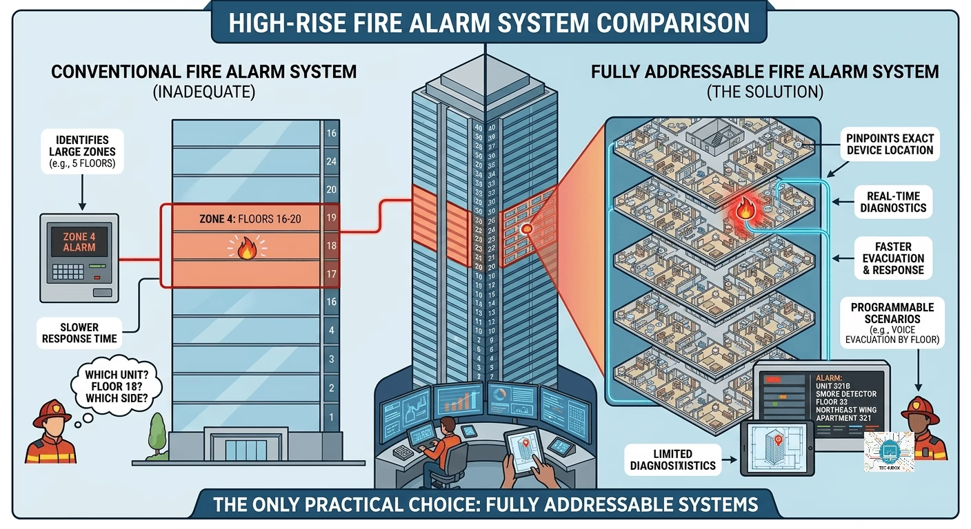
For any high-rise building, a fully addressable fire alarm system is the only practical choice. Conventional systems — which can only identify which zone has triggered, not which individual device — are completely inadequate for a 40-floor tower with hundreds of detection points.
3.1 Why Addressable?
- Individual device identification: Every detector, manual call point, and module reports its exact location to the Fire Alarm Control Panel (FACP)
- Faster investigation and response: Engineers and fire wardens can immediately locate the triggered device
- Fault isolation: A single device fault does not disable an entire zone
- Loop survivability: Modern addressable systems operate on Class A (Style 6/7) or Class B (Style 4) wiring topologies with fault tolerance
- Remote programming and diagnostics: Sensitivity adjustment, event logging, and remote monitoring without physical site visits
3.2 Loop Architecture and Capacity
Most modern addressable fire alarm panels (e.g., Notifier NFS2-3030, Honeywell FS90, Bosch FPA-5000, or Hochiki FIREwave) operate on SLC (Signalling Line Circuit) loops, each supporting 50 to 250+ addressable devices per loop.
| Building Height | Typical Floors | Recommended Loops | Panel Capacity (Min) |
| Low-rise (reference) | Up to 10F | 1–2 loops | 1 loop panel |
| Medium high-rise | 10–25F | 2–4 loops | 2-loop expandable panel |
| Tall high-rise | 25–50F | 4–8 loops | Network panel with repeaters |
| Super high-rise | 50F+ | 8–16 loops | Networked multi-panel (peer-to-peer) |
DESIGN RULE: Never load an SLC loop above 80% of its rated device capacity. Leave headroom for future devices and to reduce loop resistance stress.
4. Zoning Strategy for High-Rise Buildings
Zoning defines how the building is divided into discrete areas for alarm signalling and evacuation management. In a high-rise, zoning strategy directly drives your evacuation model.
4.1 Vertical vs. Horizontal Zoning
- Horizontal zoning: Each floor (or portion of a floor) forms its own zone — standard approach for offices and hotels
- Vertical zoning: A riser shaft, stairwell, or service core spanning multiple floors forms a single zone — used for void spaces and risers
- Combined zoning: Common in mixed-use towers where each tenancy type has its own zone hierarchy
4.2 Recommended Zone Groupings
| Zone Type | Coverage Area | Notes |
| Floor Zone | One zone per floor (or per half-floor >1000 m²) | Primary evacuation trigger unit |
| Stairwell Zone | Each stairwell as individual zone | Smoke detection critical for evacuation routes |
| Lift Lobby Zone | All lift lobbies on a floor | Recall logic triggers on this zone |
| Basement Zone | B1, B2 etc. individually | Car parks need aspirating or beam detectors |
| Plant Room Zone | Per plant room or floor cluster | High heat environments — use heat detectors |
| Roof / Plantroom | Combined or individual | Limited access — maintenance attention zone |
5. Detector Selection by Location
Detector selection in a high-rise is far more nuanced than a standard commercial building. Each space has its own fire signature, ambient conditions, and false alarm risk profile.
| Location | Recommended Detector Type | Reason |
| Open plan offices | Optical smoke detector | Early detection of smouldering fires; low false alarm rate |
| Server rooms / IT spaces | Very Early Warning (VESDA aspirating) | Sub-threshold smoke detection before visible smoke |
| Kitchens / Canteens | Rate-of-rise heat detector (A2R) | Smoke detectors would false alarm from cooking fumes |
| Car parks / Basements | Linear beam detector or CO/NO2 sensor | Open volumes — beam spans large areas efficiently |
| Stairwells | Multi-criteria detector (smoke+heat) | Must not false alarm; stairwell smoke = critical event |
| Plant rooms | Fixed temperature heat detector (Grade A1) | High ambient temperatures — optical detectors unreliable |
| Atriums / High ceilings | Aspirating smoke detection (ASD) or beam | Smoke dilutes at height — standard point detectors miss it |
| Lift shafts | Heat detector at top of shaft | Smoke rises into shaft — heat detector preferred |
| Hotel bedrooms | Optical smoke + CO combined | Sleeping risk + smouldering bedding scenario |
| Corridor / escape routes | Optical smoke detector | Early warning for evacuation path protection |
GCC NOTE: Saudi Civil Defence requires detector coverage in ALL normally occupied areas without exception. False alarm management must be addressed through detector selection, not by omitting coverage.
6. Manual Call Points (MCP) — Siting Rules
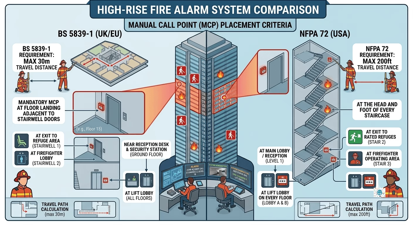
Manual Call Points must be positioned so that no person in any occupied area needs to travel more than 30 metres (BS 5839-1) or 200 feet (NFPA 72) to reach one. In a high-rise, this typically means:
- At every floor landing adjacent to stairwell doors — mandatory
- At exits to refuge areas and firefighter lobbies
- At the head and foot of every staircase
- Near main reception desks and security stations
- At lift lobby positions on every floor
MCPs must be at 1.4 m mounting height (centre of faceplate) and clearly colour-coded red. In GCC projects, Arabic labelling is typically required alongside English.
7. Evacuation Strategy: Phased Evacuation
Total simultaneous evacuation of a high-rise is dangerous. Stairwells become congested, evacuation time is extended, and false alarms cause complacency among repeat partial evacuees. The industry standard is Phased (or Progressive Horizontal) Evacuation.
7.1 How Phased Evacuation Works
- Stage 1 — Alarm in Fire Floor: Occupants on the fire floor evacuate immediately. The floor above and floor below are placed on Alert (pre-warning sounder or PA announcement only)
- Stage 2 — Extending Alert: If the fire is confirmed or spreads, the alert zone expands to additional floors above and below
- Stage 3 — General Evacuation: If required, a full building evacuation is initiated — usually by fire service command
BS 5839-1 Clause 18.2 specifically addresses phased evacuation and requires that the fire alarm system be capable of selectively alerting individual zones without triggering a general alarm. This requires programmable cause-and-effect logic in the FACP.
7.2 Cause and Effect (C&E) Matrix
The C&E matrix is the engineering document that programs the FACP behaviour. For a high-rise, a typical C&E entry might read:
- IF: Detector in Zone 12 (Floor 12) activates
- THEN: Sounders in Zone 12 = Evacuation tone; Zone 11 and Zone 13 = Alert tone; All other floors = No change
- AND: Lift Recall activates for all lifts serving Floor 12; BMS receives alarm signal on Floor 12 output
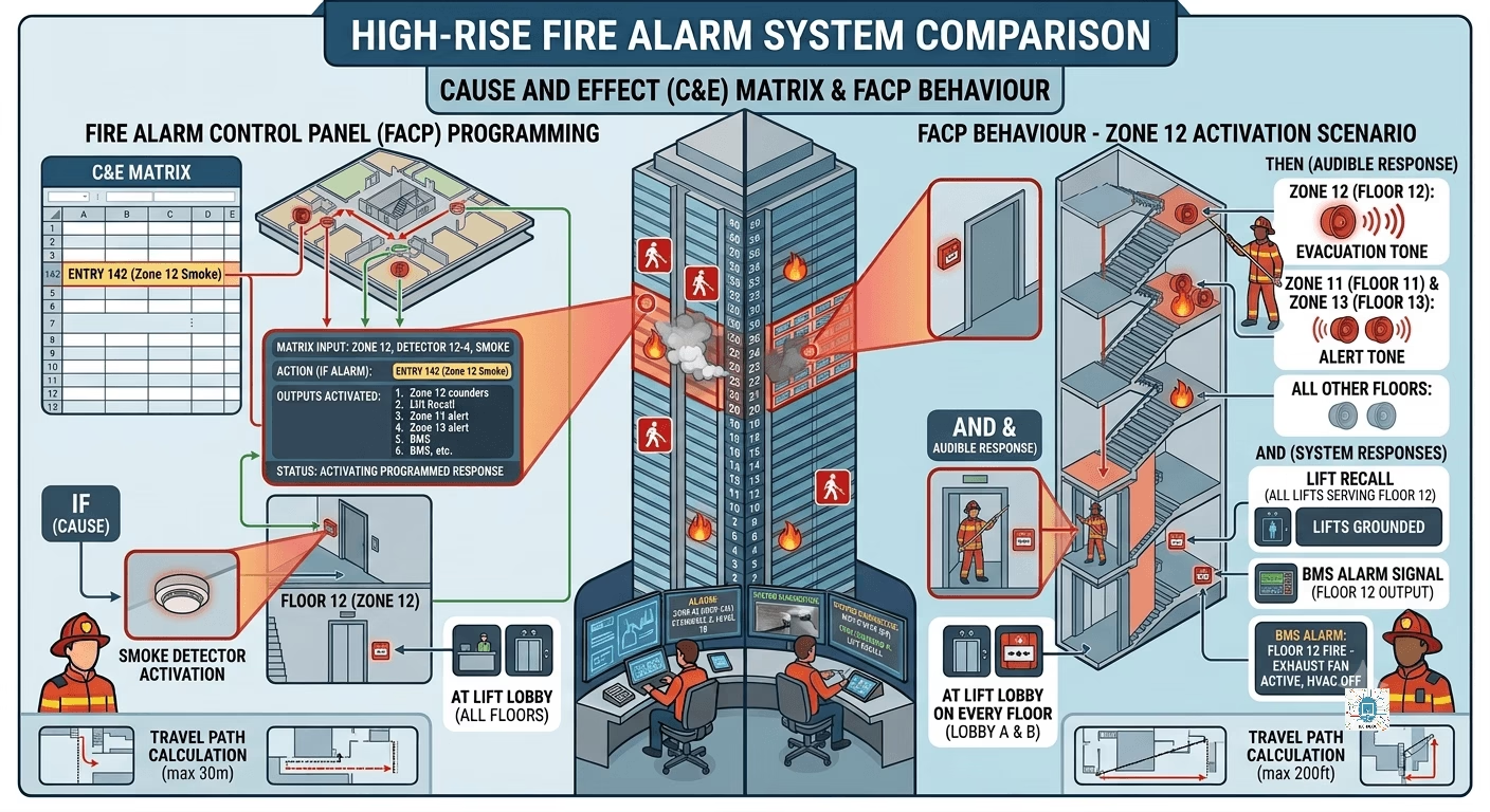
The C&E matrix is one of the most critical deliverables in a high-rise fire alarm design package. It must be reviewed and approved by the engineer, client, and AHJ before FACP programming commences.
8. Voice Alarm (VA) / Public Address Integration
In a high-rise building, audible tone sounders alone are insufficient. Occupants on upper floors may not understand what the alert tone means, and tone-only systems cannot communicate phased evacuation instructions. Voice Alarm (VA) systems — governed by EN 60849 and NFPA 72 Chapter 24 — are a mandatory requirement in most high-rise projects.
8.1 VA System Requirements for High-Rise
- Intelligibility: STI-PA (Speech Transmission Index for Public Address) must achieve a minimum of 0.5 (Good) in all occupied areas — tested to IEC 60268-16
- Coverage: Every occupied space must receive intelligible voice coverage — not just corridors
- Power amplification: Minimum 100V line distribution; N+1 amplifier redundancy required
- Pre-recorded messages: Standard fire evacuation messages in multiple languages (English + Arabic mandatory in KSA/UAE)
- Live microphone override: From a Fire Control Room or security desk, for live announcements
- Zoned paging: Ability to address individual floors or floor groups independently
8.2 VA System Architecture
In most GCC high-rise projects, the VA system is integrated with the fire alarm panel — meaning fire detection events automatically trigger pre-programmed voice messages to specific zones. The VA system must be certified under EN 54-16 (voice alarm control) and EN 54-24 (loudspeakers).
CRITICAL: VA loudspeaker circuits must be fault-monitored at every circuit. A single speaker fault must be detected and reported without affecting the rest of the system. This typically requires end-of-line devices or supervised wiring.
9. Wiring Topologies and Cable Selection
9.1 SLC Loop Wiring — Class A vs Class B
| Topology | NFPA 72 Class | BS 5839 Style | Fault Tolerance | Use in High-Rise |
| Ring (loop) | Class A | Style 6 | Single open/short — system continues | Mandatory for all floors above Ground |
| Spur (stub) | Class B | Style 4 | Open fault — devices past fault lost | Acceptable only for small isolated areas |
| Class X | Class X | Not in BS | Open + short simultaneously tolerated | Critical applications: hospitals, data centers |
9.2 Cable Specification
- SLC/Signalling cables: 1.5 mm² twisted pair, screened (LSZH sheath) — minimum
- Fire survival cables: All sounder, VA, and call point circuits in high-rise must use FP200 Gold or equivalent (IEC 60331 compliant) — circuit integrity maintained at 650°C for 3 hours
- Cable segregation: Fire alarm cables must not share containment with power cables (min. 300 mm separation or use of dedicated metal conduit)
- Conduit: All exposed cable in plant rooms, risers, and basements to be in steel conduit, minimum 20 mm diameter
BS 5839-1 Clause 26 requires enhanced cable fire survival performance for systems in high-rise buildings. Do not specify standard PVC-insulated cables for any life-safety circuit.
10. Fire Alarm Control Panel (FACP) Location and Specification
10.1 FACP Siting Requirements
- Ground floor, adjacent to the main building entrance accessible to the fire brigade
- In a dedicated fire control room (preferred for buildings over 30m) — per BS 9999 and NFPA 72
- Room must be fire-rated (minimum 60 minutes), ventilated, and accessible 24/7
- FACP must be visible from the room entrance — no obstructions
- Repeater panel at security desk and any other continuously staffed position
10.2 Panel Specification Checklist
- Full addressable — EN 54-2 certified (for BS 5839 projects) or UL listed (for NFPA 72 projects)
- Minimum 2 SLC loops with expansion capacity to 8+ loops
- Built-in event log: minimum 1,000 events with date/time stamp
- Networked capability: TCP/IP or peer-to-peer network for multi-panel configurations
- Integrated BMS output: dry contacts, RS-485 Modbus, BACnet, or TCP/IP
- Battery backup: 24-hour standby + 30-minute alarm (BS 5839-1 Clause 25 / NFPA 72 Table 10.6.7.2)
- Colour touchscreen display with floor plan integration (recommended for high-rise)
11. BMS and Third-Party System Integration
A fire alarm system in a high-rise building does not operate in isolation. It must interface with multiple building systems — and these integrations must be engineered with fail-safe logic.
| Integrated System | Fire Alarm Action | Interface Method |
| Lift / Elevator | Recall all lifts to ground on general alarm; lock out non-firefighter lifts | Dry contact relay to lift controller |
| HVAC / AHU | Shut down supply/return air handling; activate smoke dampers in fire zone | BMS relay or direct relay output |
| Pressurisation fans | Activate stairwell / lift lobby pressurisation on alarm | Direct relay — must be fast acting (<10 sec) |
| Access Control | Release all electromagnetic door holders on alarm; unlock fire escape routes | Fail-safe relay — power cut releases door |
| Smoke curtains | Deploy smoke curtains in atria and corridors on zone alarm | Relay output from FACP zone module |
| BMS (overall) | Transmit alarm, fault, and zone status to BMS for monitoring | BACnet/IP, Modbus RTU, or dry contacts |
| CCTV | Trigger camera presets to fire zone on alarm — auto-display on control room monitor | TCP/IP integration or relay trigger |
| Sprinkler system | Receive waterflow switch signal; display as alarm input on FACP | Monitor module on SLC loop |
| Generator / UPS | No shutdown during fire alarm; integrate with emergency power logic | Interlock via building electrical panel |
DESIGN CAUTION: Every third-party integration must be documented in the C&E matrix and tested during commissioning. Integration failures are one of the most common — and most dangerous — gaps found during fire alarm witness tests.
12. Refuge Areas and Disabled Persons Fire Alarm Systems
High-rise buildings must provide refuge areas — protected spaces where mobility-impaired occupants can wait for assisted evacuation. The fire alarm system must interface with these spaces.
- Two-way voice communication between refuge area and fire control room — mandatory per BS 5839-9
- Refuge call points: Wall-mounted push button and speaker/microphone unit in every refuge area
- Visual alarm devices (VADs): Flashing beacons in all areas where audible alarms may not be heard by hearing-impaired occupants
- VADs must comply with BS EN 54-23 for photometric output
- Combined audio/visual devices are preferred to reduce surface mounting hardware
13. False Alarm Management
False alarms in a high-rise are not just an inconvenience — they erode occupant trust, lead to stairwell injuries during unnecessary evacuations, and potentially cause financial liability. A robust false alarm management strategy must be built into the design from the outset.
13.1 Technical Measures
- Detector type selection: Multi-criteria detectors in areas prone to nuisance — kitchens, plant rooms
- Alarm confirmation (coincidence detection): Require 2 detectors in the same zone to activate before triggering alarm — particularly in unoccupied areas overnight
- Alarm verification delay: Configurable time delay (typically 30–60 seconds) before alarm is escalated — to allow investigation
- Cause investigation mode: Enable attending staff to silence local sounders and investigate before full building alarm
13.2 Procedural Measures
- Appoint a Responsible Person for false alarm investigation and reporting
- Maintain a false alarm log — if a system generates more than 25 false alarms per year per 1,000 devices, the design must be reviewed (BS 5839-1 Annex H guidance)
- Hot-work permit system: Isolate detectors during welding, cutting, or painting with FACP-documented isolations
14. Testing, Commissioning, and Handover
A high-rise fire alarm commissioning programme is a substantial undertaking. For a 40-floor tower with 600+ devices, expect 3–5 days of device testing alone, followed by a full system witness test.
14.1 Device-Level Testing
- Every detector: Function test using aerosol (optical/multi-criteria) or heat gun (heat detectors)
- Every MCP: Test key operation and verify address at FACP
- Every sounder and VA speaker: Sound level test with calibrated meter — minimum 75 dB(A) at 1m or 5 dB above ambient (whichever is greater)
- Every VAD: Verify flash rate and photometric output per EN 54-23
14.2 System-Level Testing
- C&E matrix verification: Test every cause-and-effect entry by simulating alarm in each zone and verifying correct outputs
- BMS integration test: Confirm every integration point — lift recall, damper closure, pressurisation activation
- Network failover test (multi-panel): Disconnect network link; confirm local panel continues to operate independently
- Battery backup test: Disconnect mains power; confirm 24-hour standby without failure
- VA intelligibility test: STI-PA measurement in representative rooms across all floors
HANDOVER DOCUMENTS REQUIRED: As-built drawings, C&E matrix (final), device schedule with addresses, test certificates, O&M manual, maintenance schedule, and AHJ approval certificate. In KSA, Civil Defence sign-off certificate is mandatory before building occupancy.
15. Common Design Mistakes to Avoid
| Mistake | Consequence | Correct Approach |
| Using Class B (spur) wiring throughout | Single cable fault disables large areas | Use Class A ring topology on all occupied floors |
| Specifying optical detectors in kitchens | Constant false alarms from cooking fumes | Use A2R heat detectors in cooking areas |
| Omitting VA system in favour of tone-only sounders | Occupants cannot understand phased evacuation instructions | Design integrated VA from the outset |
| Under-specifying battery backup | System fails within hours of mains loss | 24-hour standby + 30 min alarm — non-negotiable |
| No alarm confirmation logic in unoccupied areas | Single detector activation causes full building alert at 3 AM | Program coincidence detection for unoccupied zones |
| Incomplete C&E matrix at handover | BMS integrations not working; lifts not recalled | C&E matrix must be signed off before programming |
| Detector installed in dead air spaces | Smoke never reaches detector | Follow EN 54-7 spacing rules; avoid ceiling obstructions |
Conclusion
Designing a fire alarm system for a high-rise building is one of the most technically demanding assignments in the ELV and M&E engineering domain. It requires a thorough understanding of evacuation behaviour, detector technology, loop architecture, standards compliance, and multi-system integration — all while managing the practical realities of cable routing, commissioning access, and coordination with other trades.
The principles outlined in this guide — addressable architecture, phased evacuation, Class A wiring, voice alarm integration, and a rigorously tested C&E matrix — form the foundation of a system that will perform reliably in an actual emergency. In a high-rise, there is no room for shortcut specifications.
If you are working on a high-rise fire alarm project in the GCC and need to review your design against Saudi Civil Defence or NFPA 72 requirements, refer to our related articles on BS 5839 vs NFPA 72 and Fire Alarm Integration with BMS — available on techubox.com.