Complete Technical Guide for Thermal Camera
Why Thermal Cameras Are No Longer Optional
Walk any perimeter fence in a Saudi industrial facility at 2 AM and you will understand the problem immediately. Standard IP cameras — even top-tier 4K models — are blind in the dark. An infrared-illuminated camera helps, but IR light bounces back from fog, sand haze, and reflective surfaces. A thermal camera, on the other hand, does not care about ambient light at all. It reads heat, and heat does not disappear when the sun goes down.
Thermal imaging has become a baseline requirement in serious security specifications. Once you understand the physics, the product lines, and the practical installation considerations, a thermal deployment is no more complex than any other IP camera project.
This article covers everything: the physics of infrared thermography, sensor types and specifications, product selection, cable and network design, mounting and alignment, software configuration, and a full DIY commissioning walkthrough. Whether you are specifying a border perimeter or a server room, by the end of this guide you will have the knowledge to do it properly.
The Physics of Thermal Imaging
1.1 What Is Infrared Radiation?
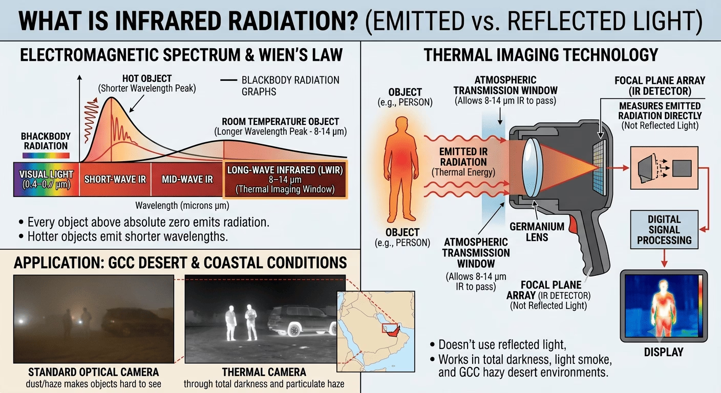
Every object above absolute zero emits electromagnetic radiation. The wavelength of that radiation is inversely proportional to temperature — hotter objects emit shorter wavelengths, cooler ones emit longer. Human-visible light spans roughly 0.4–0.7 µm (microns). Thermal imaging exploits the long-wave infrared (LWIR) band: 8–14 µm. This is where room-temperature objects — people, vehicles, machinery — emit peak radiation, and critically, where the Earth’s atmosphere has a transmission window that allows thermal energy to travel without being absorbed.
Thermal cameras do not produce an image from reflected light. They measure emitted radiation directly. This is why they work in total darkness, through light smoke, and in the hazy particulate conditions common across GCC coastal and desert environments.
1.2 Emissivity
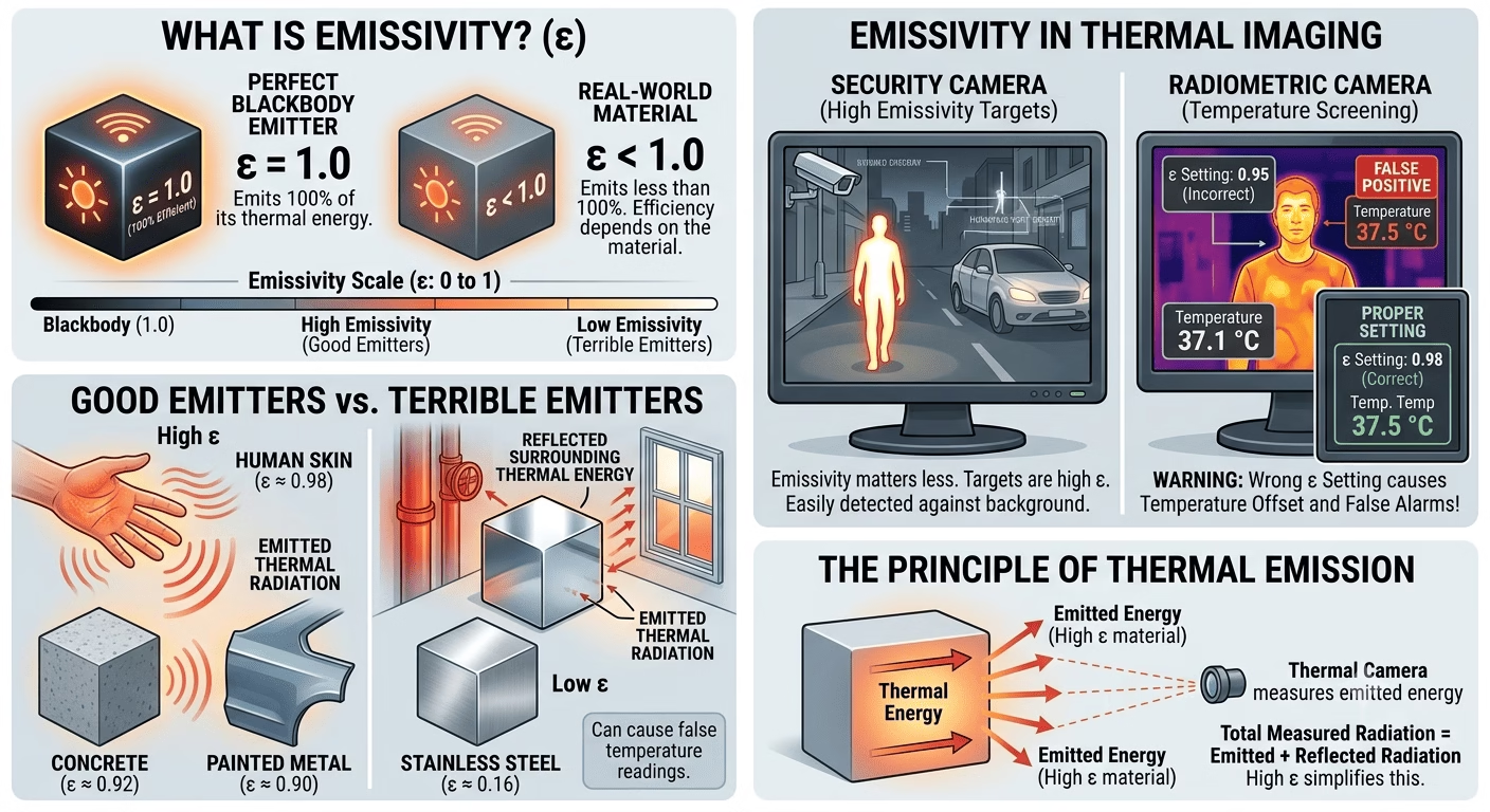
Emissivity (ε) is a material’s efficiency in emitting thermal radiation, expressed as a ratio from 0 to 1. A perfect blackbody emitter has ε = 1.0. Most natural surfaces — human skin (ε ≈ 0.98), concrete (ε ≈ 0.92), painted metal (ε ≈ 0.90) — are good emitters. Bare polished metals (aluminium ε ≈ 0.05, stainless steel ε ≈ 0.16) are terrible emitters. They reflect thermal energy from surrounding objects rather than emitting their own, which causes false readings and can make them appear the same temperature as their background.
For a security camera, emissivity matters less than for a precision temperature measurement device. Human bodies and vehicle bodywork are high emissivity targets and appear clearly against most backgrounds. Where emissivity becomes an issue is in radiometric cameras used for temperature screening — the wrong emissivity setting will produce a temperature offset that causes false alarms.
1.3 LWIR vs. MWIR
| Parameter | LWIR (8–14 µm) | MWIR (3–5 µm) |
| Detector cost | Low — uncooled microbolometer | High — cooled detector required |
| Typical application | Security & surveillance, building diagnostics | High-end military, scientific |
| Performance in heat | Excellent; people and vehicles always visible | Can saturate in very hot scenes (deserts) |
| Power consumption | Low (no cooling needed) | High (Stirling cooler draws 10–30 W) |
99% of GCC security projects, LWIR uncooled cameras are the correct and cost-effective choice. MWIR is reserved for military and specialised scientific applications. This guide focuses on LWIR.
Sensor Technology and Key Specifications
2.1 The Uncooled Microbolometer
The detector at the heart of a modern security thermal camera is a microbolometer focal plane array (FPA). Each pixel in the array is a tiny resistive element whose electrical resistance changes with temperature. When thermal radiation from the scene strikes the array, the resistance pattern is read out and converted to a temperature map. The entire process happens at room temperature — no cryogenic cooling required.
The FPA is mounted inside a hermetically sealed housing, vacuum-packaged to prevent oxidation of the delicate resistive elements and to eliminate the convective heat transfer that would swamp the tiny temperature signals. This vacuum package is the single most expensive component in an uncooled thermal camera, and it is why dropping a thermal camera is a much more serious event than dropping a standard IP camera.
2.2 Resolution
Thermal sensor resolutions are much lower than standard IP cameras. Common formats are:
- — Entry-level, short-range detection, typically under 50 m
- — Mid-range, most common in perimeter security, effective to 150–300 m
- — High-end security, critical infrastructure, wide perimeter coverage
- — Specialist long-range, premium pricing
Do not compare these numbers directly with visible-light IP cameras. Thermal energy signatures are inherently broader than light reflections, and a 320×240 thermal camera at 50 m gives excellent human detection. The critical metric is pixel pitch combined with focal length, not megapixels.
2.3 Pixel Pitch
Pixel pitch — the physical size of each detector element — determines sensitivity and image quality. Common values are 17 µm and 12 µm. A 17 µm pitch sensor is easier to manufacture and typically more affordable. A 12 µm pitch in the same format size allows a shorter focal length lens for a wider field of view, producing more compact camera designs. For equal focal lengths, 12 µm pitch gives slightly inferior thermal sensitivity (NETD) compared to 17 µm.
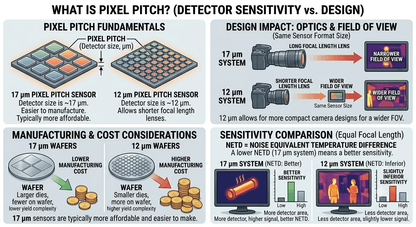
2.4 NETD — Thermal Sensitivity
Noise Equivalent Temperature Difference (NETD) is the most important sensitivity specification. It defines the smallest temperature difference the sensor can reliably detect, measured in millikelvin (mK). Lower NETD is better.
- — High sensitivity; excellent for detecting cool intruders against warm backgrounds or subtle heat anomalies in mechanical inspection
- — Good for standard perimeter security; most mid-range products fall here
- — Budget-grade; acceptable only for short-range, high-contrast scenes
⚙ Field Note: In the GCC summer, ambient temperatures above 40°C reduce the thermal contrast between a human body (37°C) and the environment. A camera rated < 40 mK NETD will maintain reliable detection where a 100 mK camera may struggle. Always specify NETD carefully for Middle East deployments.
2.5 Field of View and Focal Length
Thermal lenses are specified by focal length (mm) just like standard cameras. Field of view (FOV) is calculated from the focal length and the sensor dimensions. A 320×240 sensor with 17 µm pixel pitch has a physical sensor size of 5.44 mm × 4.08 mm. A 13 mm focal length lens gives approximately 23° × 17° FOV. A 35 mm lens gives approximately 9° × 6°.
Most thermal cameras use fixed lenses. Motorized zoom is available but expensive. Plan your coverage geometry carefully before ordering — you cannot reconfigure lens FOV in the field the way you can pan a PTZ camera.
2.6 The DRI Range Model
The standard framework for specifying detection range is Detection-Recognition-Identification (DRI), based on the Johnson Criteria:
- — An object is present. Requires 1.5–2 pixels on target.
- — Object class identified (human vs. vehicle). Requires 6 pixels on target.
- — Specific identity (individual person). Requires 13 pixels on target.
For perimeter security, detection range is the primary specification. Use the manufacturer’s DRI tables or the RAGE (Range Angle Geometry Engine) calculator for accurate estimates. As a rough field rule: a 320×240 camera with a 13 mm lens detects a standing human at approximately 180–220 m under clear conditions.
Product Types and GCC Market Overview
3.1 Fixed Thermal Cameras
The most common form factor: a ruggedized housing containing the thermal sensor, lens, processing board, and network interface. Available in bullet, box, and dome form factors. For perimeter work, bullet or dedicated outdoor housings with sunshields are standard. Operating temperature range should be confirmed for GCC conditions — surface temperatures on a south-facing enclosure can exceed 75°C in summer.
3.2 Bi-Spectrum (Thermal + Optical) Cameras
These combine a thermal channel and a standard visible-light sensor in one housing. The thermal channel triggers alarms; the optical channel provides full-color video evidence for the human operator who responds to the alert. The best bi-spectrum cameras offer pixel-aligned fusion — the two images are spatially registered so that a detected object appears in exactly the same position in both channels. This is a significant advantage for operator training and alarm verification.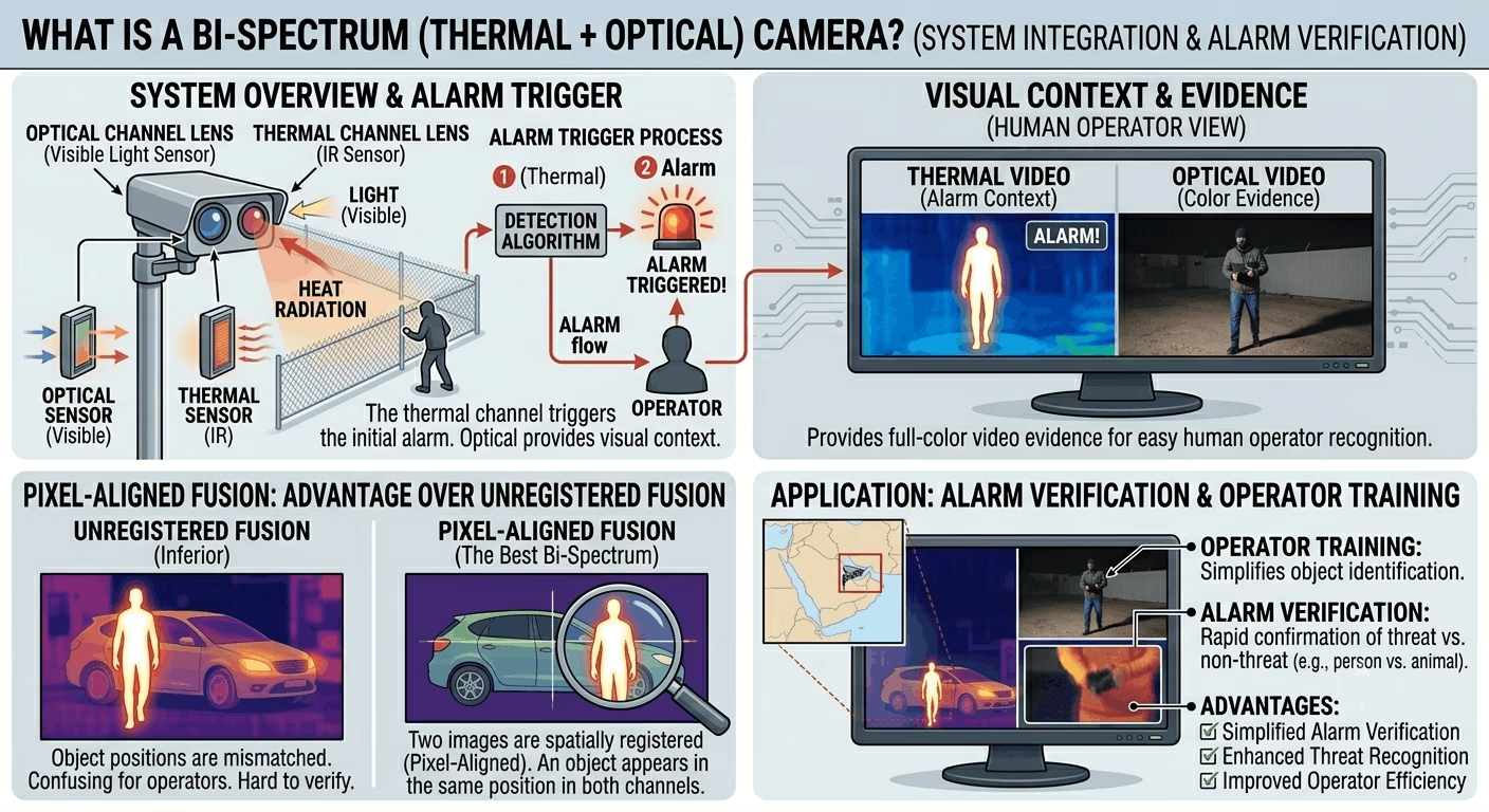
⚙ Field Note: In GCC projects, bi-spectrum cameras on perimeter fences dramatically reduce false alarm rates from vegetation, animals, and heat shimmer, because the guard can instantly see both the thermal detection and the visible image to make a judgment call.
3.3 Thermal PTZ Cameras
Pan-Tilt-Zoom thermal cameras are high-value assets used on tower-mounted positions for wide-area surveillance. They typically combine a high-resolution thermal sensor (640×480 or higher) with continuous rotation capability, speed dome mechanics, and laser rangefinders in premium configurations. Integration with radar systems for automatic slew-to-cue is common in critical infrastructure projects.
3.4 Radiometric Cameras (Temperature Measurement)
Standard thermal cameras produce a relative thermal image — a map of temperature differences. Radiometric cameras add absolute temperature measurement capability: each pixel stores an actual temperature value in degrees Celsius. These cameras are used for fire detection (monitoring hotspots in waste compactors, battery rooms, power substations) and for people-screening applications.
⚠ Warning: Radiometric cameras require calibration against known temperature references. An uncalibrated or incorrectly set radiometric camera will generate false alerts or miss real thermal events. Always commission radiometric deployments with the calibration tools provided by the manufacturer.
3.5 Major Brands in GCC Market
| Brand | Key Thermal Range | Strengths | Notes |
| Hikvision | DS-2TD series, DeepinView | Price, ecosystem, AI integration | Very strong in GCC projects |
| Dahua | TPC series, Pro AI Thermal | Cost-effective, good VMS | Growing GCC presence |
| Axis | Q19, Q29 series | ACAP apps, reliability, ONVIF | Premium; widely used in critical infra |
| Bosch | FLEXIDOME, MIC IP | Fire detection integration, IVA | Strong in industrial GCC |
| Pelco | Sarix Thermal, Spectra | PTZ thermal specialist | Legacy installs across KSA |
| FLIR (Teledyne) | Elara, Quasar, Triton | Military pedigree, long-range | Premium pricing, critical border use |
Applications in GCC Security Projects
4.1 Perimeter Intrusion Detection
The flagship application. Thermal cameras mounted at 3–6 m height on fence posts or dedicated poles provide detection zones 150–400 m long per camera, depending on lens selection. Combined with video analytics (virtual tripwires, area intrusion rules), they deliver reliable detection with minimal false alarms from vegetation movement — a major problem with passive IR beam detectors in the windy GCC desert environment.
4.2 Oil, Gas & Petrochemical Facilities
Thermal cameras are used for both security and process monitoring in refinery and gas plant environments. Fire and gas release produces a distinctive thermal signature detectable long before a flame becomes visible. Radiometric cameras mounted on process areas can monitor equipment for abnormal heat buildup — overheating motors, blocked heat exchangers, failing pipeline insulation — providing predictive maintenance data as a secondary benefit alongside security coverage.
4.3 Airport & Port Perimeters
GCAA and GACA aviation security regulations in the UAE and KSA specify thermal imaging as part of the layered perimeter security requirement for international airports. Port security across Dubai, Jebel Ali, Dammam, and other GCC hubs increasingly requires thermal perimeter coverage as part of ISPS compliance. These are always integrated with PSIM platforms — ensure your thermal cameras are ONVIF Profile S and T compliant and support standard alarm/event APIs.
4.4 Data Centers and Server Rooms
Radiometric thermal cameras inside server halls provide continuous hotspot monitoring across server racks without physical contact sensors. A single wide-angle 640×480 camera can monitor dozens of rack fronts, triggering alerts when any zone exceeds a configurable threshold. This supplements building management system (BMS) temperature sensors, which typically have 2–5-minute scan cycles and fixed-point measurement only.
4.5 People Screening (Fever Detection)
During and post-COVID-19, radiometric cameras were deployed at building entrances across the GCC for skin temperature screening. These require a calibrated blackbody reference target in the camera’s field of view to maintain temperature accuracy. Without a reference blackbody, temperature drift from ambient conditions can easily produce 1–2°C errors that cause either missed detections or unacceptable false alarm rates.
4.6 Critical National Infrastructure
Power transmission towers, water treatment plants, desalination facilities, and communications infrastructure across KSA, UAE, and Qatar are increasingly spec’d with thermal cameras as part of CNI protection requirements under national security frameworks. Integration with radar systems for auto-track of detected targets is common at this level.
System Design Principles
5.1 Coverage Planning
Start with a scaled site map. Mark all critical assets, fence lines, and entry points. Identify the detection range requirement for each zone. Then work backward from the DRI range table to select the correct lens and sensor format. For linear perimeter applications, cameras should provide overlapping coverage of at least 20% — if a 300 m detection zone requires 5 cameras at 60 m each, space them so that the edge of camera 1’s zone overlaps the start of camera 2’s by at least 50 m.
5.2 Mounting Height and Angle
Optimal mounting height for perimeter cameras is 3–5 m on a rigid pole or wall bracket. Too low and the field of view is broken by terrain undulations and vegetation. Too high and the angle become steep, reducing the effective range across the ground plane. The recommended depression angle for a horizontal perimeter is 5–15°. Tilt angle has a significant effect on range — every degree of additional downward tilt reduces the ground-plane detection range proportionally.
5.3 Environmental Factors in GCC
The GCC environment creates specific challenges for thermal camera deployment:
- — In summer afternoons, ground and air temperatures can equalize, reducing the temperature contrast of a walking human against the background. Specify cameras with NETD < 40 mK for critical perimeter coverage.
- — Use cameras with IP66 or IP67 rating minimum. IP68 is preferable for cameras in exposed desert locations. Check the window material — Ge (germanium) windows are standard in LWIR cameras and are durable, but accumulation of fine dust on the window reduces sensitivity; regular cleaning schedules are essential.
- — Camera housings must include sun shields (visors) to prevent direct solar heating of the housing, which can raise internal temperatures beyond the rated operating range. Specify stainless steel sun shields for coastal environments.
- — In industrial areas, heavy machinery causes ground vibration that leads to image jitter and increased false alarm rates from video analytics. Use vibration-damped mounting brackets.
5.4 Network Design
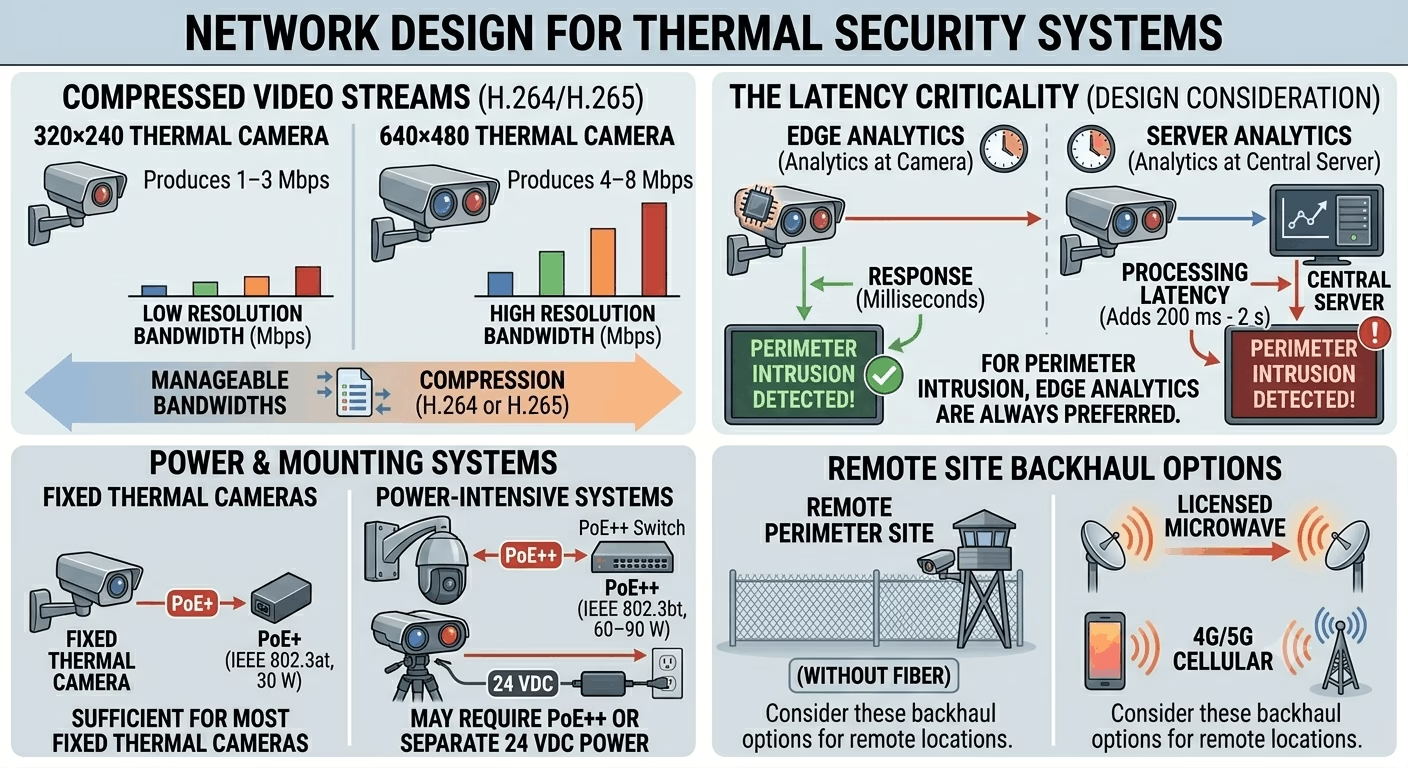
Thermal cameras transmit H.264 or H.265 compressed video streams. A 320×240 thermal camera typically produces 1–3 Mbps; a 640×480 camera produces 4–8 Mbps. These are manageable bandwidths. The critical design consideration is latency — video analytics running at the camera (edge analytics) respond in milliseconds; analytics running on a central server add 200 ms to 2 s of processing latency. For perimeter intrusion, edge analytics are always preferred.
For remote perimeter sites without fibre, consider licensed microwave or 4G/5G cellular backhaul. PoE+ (IEEE 802.3at, 30 W) is sufficient for most fixed thermal cameras. Thermal PTZ cameras and binocular thermal/optical systems may require PoE++ (IEEE 802.3bt, 60–90 W) or separate 24 VDC power.
DIY Installation: Step-by-Step Guide
This section walks through a complete thermal camera installation from unboxing to commissioning. The example uses a mid-range bi-spectrum thermal/optical bullet camera (320×240 thermal, 2MP optical) installed on a perimeter fence post. The same principles apply to all fixed thermal cameras.
Step 1 — Tools and Materials Required
- Thermal camera unit (confirm delivery of lens, mounting bracket, and sealing accessories)
- PoE+ network switch or PoE injector (IEEE 802.3at minimum; check camera power draw)
- Cat6 shielded (STP) cable — use outdoor-rated, UV-stabilized, gel-filled for direct-burial runs
- RJ45 crimping tool and shielded RJ45 connectors
- IP67-rated outdoor junction box for cable entry point
- Stainless steel mounting pole or wall bracket (galvanized or SS316 for coastal sites)
- Cable conduit — HDPE corrugated for underground sections, GI conduit for above-ground
- Spirit level, drill, core drill (for wall penetrations), spanner set
- Laptop or tablet with web browser for camera configuration
- Network tester
- Multimeter for power verification
✔ Pro Tip: For outdoor thermal cameras, always use STP (shielded twisted pair) cable terminated with shielded connectors. Unshielded cable in perimeter environments picks up interference from lightning conductors and heavy machinery, causing intermittent network dropouts.
Step 2 — Site Survey Before Installation
Do not skip this step. Walk the intended camera location at dusk or at the same time the camera will typically be active.
- Verify line-of-sight to the coverage zone — thermal cameras cannot see through solid walls or dense shrubs
- Check for heat sources that may cause interference: HVAC units, floodlights, vehicle idling areas directly in the FOV
- Confirm cable route from camera to network switch/NVR location
- Assess pole/wall structural integrity for bracket attachment
- Check for any permit requirements for pole installation (municipality, landlord, site HSE)
⚠ Warning: Never mount a thermal camera directly adjacent to a high-power sodium or LED floodlight. The heat from the lamp housing will bleed into the thermal image and create a persistent blind spot. Maintain at least 1.5 m separation.
Step 3 — Cable Installation
- Mark cable route from camera location to IDF/network room.
- Where cable runs underground, bury in HDPE conduit at minimum 600 mm depth. Use cable warning tape at 300 mm depth above the conduit.
- For above-ground runs along fences or walls, use GI conduit with UV-stable saddle clamps at maximum 400 mm spacing.
- Terminate the network-room end into a patch panel or directly into a PoE switch port. Label clearly: camera ID, location, date installed.
- At the camera end, leave 600 mm of slack inside the junction box for re-termination.
- Test cable with a cable tester before camera mounting. Record wire map, length, and attenuation. Maximum run length for Cat6 PoE is 100 m (90 m permanent link + 10 m patch cables).
⚙ Field Note: In GCC installations, cable runs in conduit exposed to direct sun can reach 70–75°C in summer. Use cable rated to 80°C minimum. Cat6 outdoor UV-rated cables meeting IEC 60332-1 fire rating are available from major suppliers.
Step 4 — Mounting the Camera
- Install the mounting bracket on the pole or wall surface using stainless steel hardware (M8 minimum). Torque to bracket manufacturer’s specification.
- Apply a thin bead of silicone sealant around any wall penetrations before fitting the conduit entry.
- Hang the camera body on the bracket — do not tighten fully yet.
- Route the cable tail from the junction box into the camera’s cable entry port. Apply the supplied cable gland compression fitting tightly. Do not over-tighten — most camera glands are designed for specific cable outer diameters.
- Connect the RJ45 plug to the camera’s network port. Fit the weatherproof RJ45 boot/shroud if supplied.
- Make initial coarse aiming of the camera toward the coverage zone by eye, then tighten bracket hardware to approximately 80% torque. You will fine-tune after connecting to the network.
✔ Pro Tip: Take a photograph of the cable entry and gland compression before closing the junction box. On busy sites, a photo taken at installation saves hours of troubleshooting during any future water ingress investigation.
Step 5 — Power-Up and Initial Network Connection
- Connect the PoE switch port. Check the switch PoE status indicator — it should show the correct class negotiation (usually Class 3 or Class 4 for PoE+).
- The camera will initialise over approximately 60–90 seconds. A thermal camera takes longer than a standard IP camera because the microbolometer performs a Non-Uniformity Correction (NUC) shutter cycle during boot — you will see or hear a brief mechanical click as the internal calibration shutter closes, then opens. This is normal.
- Open a web browser on a laptop connected to the same network segment. Navigate to the camera’s default IP address (varies by brand; typically 192.168.1.64 for Hikvision, 192.168.1.108 for Dahua).
- Log in with default credentials (change these immediately after access).
- Assign a static IP address in your project IP scheme and set the subnet mask and gateway.
⚠ Warning: Never leave factory default passwords on any thermal camera. Default credentials for Hikvision and Dahua cameras are publicly documented. On a site network, an unchanged default password is an open invitation.
Step 6 — Camera Configuration
The following settings should be configured on every thermal camera deployment:
6.1 Thermal Channel Settings
- — Outdoor (or specific manufacturer presets for desert/coastal environments)
- — Set to Auto. The camera performs periodic flat-field correction to maintain image uniformity. In high-ambient-temperature environments (GCC summer), more frequent NUC cycles occur — this is normal.
- — For security, White Hot is most intuitive for operators. Black Hot reduces eye strain during long monitoring sessions. Pseudo-color palettes (Iron, Rainbow) are useful for temperature measurement applications.
- — Thermal cameras include dynamic detail enhancement. Set to medium — too high produces noisy, over-processed imagery.
6.2 Optical Channel Settings (Bi-Spectrum Cameras)
- Set appropriate resolution, frame rate (25 fps recommended), and encoding profile
- Enable H.265+ to reduce storage requirements
- Configure day/night settings — set IR cut filter to Auto, threshold to the local ambient light level
6.3 Video Analytics (IVA)
On the thermal channel, configure intrusion detection rules:
- Draw a virtual perimeter zone that matches the actual physical boundary you are protecting. Keep zones tight — oversized zones generate more false alarms.
- Set target filtering — minimum size 5×5 pixels (filters out small animals and birds), maximum size appropriate for the scene.
- Configure sensitivity. Start at medium (50/100) and adjust over the first week of operation based on false alarm rate.
- Set the alarm linkage actions: email notification, FTP snapshot upload, relay output trigger (if connected), NVR recording trigger.
⚙ Field Note: On perimeter cameras across GCC industrial sites, I consistently find that analytics tuned in the office do not perform correctly in the field. Always plan a site visit during the first week of operation to review the false alarm log and retune zone boundaries and sensitivity.
6.4 Radiometric Settings (if applicable)
- Set emissivity values for target materials (use manufacturer emissivity table)
- Configure temperature alert rules: alert zone, temperature threshold, hysteresis
- If a blackbody reference is installed, enable reference compensation and enter the blackbody temperature setpoint
Step 7 — Fine-Tune Camera Aiming
- With the live thermal image visible on your laptop screen, physically adjust the camera pan and tilt to frame the coverage zone correctly.
- Verify that the zone boundary is within frame and that the expected maximum range point is visible.
- If available, walk the detection zone boundary with a colleague and verify detection at the analytics layer — confirm alarm triggers with visual confirmation on screen.
- Tighten all bracket hardware to final torque specification.
- Apply thread-lock compound (Loctite medium strength) to all external hardware fasteners.
✔ Pro Tip: Ask a colleague to walk the far edge of the detection zone while you watch the camera live view. Count the pixels they occupy at maximum range. If fewer than 4–5 pixels of person height are visible, range is at the limit — consider adjusting lens or mounting position.
Step 8 — NVR Integration and Recording Configuration
- Add the camera to your NVR or VMS using ONVIF or the manufacturer’s proprietary protocol.
- Configure continuous recording on the optical channel and event-triggered recording on the thermal channel.
- Set recording resolution and frame rate: optical at full resolution, 25 fps continuous; thermal at full resolution, 25 fps event-triggered (continuous is optional depending on storage budget).
- Confirm storage allocation. A 320×240 thermal channel at H.265 produces approximately 800 MB/day at 25 fps. A 2MP optical channel produces approximately 8–12 GB/day at 25 fps.
- Test playback from NVR to confirm both channels are recording and synced.
Step 9 — Handover Documentation
As-installed documentation is mandatory for any professional ELV handover. Record:
- Camera serial number, firmware version, and assigned IP address
- MAC address and PoE switch port number
- Cable route drawing with conduit sizes and cable lengths
- Screenshot of live thermal and optical image from commissioning date
- Analytics zone configuration screenshot
- Password record (stored securely, not in the document handed to client)
- NVR recording configuration and storage capacity
Troubleshooting Common Thermal Camera Issues
| Symptom | Likely Cause | Remedy |
| Image appears uniformly grey or ‘flat’ | NUC (shutter) cycle stuck or not completing | Reboot camera the ; if persistent, check FPA temperature sensor |
| Intermittent image blackouts | PoE power insufficient or cable length >90 m | Measure PoE supply voltage; replace cable or add midspan injector |
| Excessive false alarms from analytics | Zone too large, sensitivity too high, heat shimmer from ground | Reduce zone size, lower sensitivity, add height mask filter |
| Hot corner or vignetting in thermal image | Housing conducting heat to germanium window edge | Improve ventilation of housing; confirm sun shield is installed |
| Radiometric temperature reading offset | Emissivity set incorrectly, no blackbody reference | Recalibrate with reference blackbody; verify emissivity setting |
| Camera overheats and reboots in GCC summer | Ambient + solar gain exceeds max operating temperature | Install larger sun shield; add ventilated enclosure; consider active cooling enclosure |
| Dusty/blurred thermal image | Sand or dust on germanium window | Clean with lens cloth and isopropyl alcohol; do not use abrasives on Ge window |
⚠ Warning: Never use a standard camera lens cloth or paper tissue on a germanium (Ge) thermal window. Ge is softer than glass and scratches easily. Use only a lint-free microfibre cloth moistened with optical-grade isopropyl alcohol (99.5% IPA), and wipe in a single circular motion from centre outward.
Relevant Standards and GCC Regulatory Context
Thermal camera systems deployed on regulated sites in the GCC must comply with a layered set of international standards and local regulatory requirements:
- (series) — IP video surveillance systems. Parts 1–4 cover requirements for system design, performance specifications, video transmission protocols, and application guidelines. Thermal cameras fall under IEC 62676-2-32 (video surveillance codecs).
- — European standard for alarm systems — CCTV surveillance systems. Widely referenced in GCC project specifications, particularly in UAE and Qatar Qatari project specs that follow UK/EU standards.
- — Installation and remote monitoring of detector-activated CCTV systems. Relevant for GCC projects with 24/7 monitoring centre integration.
- — In KSA, imported thermal cameras must meet SASO product requirements. Ensure country of origin compliance and that supplier holds valid SASO certificate of conformity.
- — Fire detection thermal cameras in UAE must be listed with UAE Civil Defence if used in fire alarm applications. Security-only thermal cameras follow UAE Federal Law and local emirate municipality requirements.
- — In KSA and Bahrain, fire and industrial thermal monitoring systems are frequently specified to NFPA 72 Chapter 17 requirements for flame and heat detection.
⚙ Field Note: When bidding thermal camera projects in GCC tenders, always confirm which standards framework applies. UAE typically references EN/BS standards; KSA references a mix of SASO, NFPA, and SBC (Saudi Building Code). Qatar references QCS (Qatar Construction Specification). Mixing frameworks in one specification is common and requires careful reading.
Approximate Cost Guide (GCC Market, 2026)
Prices are approximate GCC market rates in USD. Actual pricing varies by distributor, project quantity, and brand negotiation.
| Product Type | Approx. Price (USD) | Notes |
| 160×120 fixed thermal (budget OEM) | $300 – $600 | Short range, limited analytics |
| 320×240 fixed thermal (mid-range, Hikvision/Dahua) | $800 – $1,500 | Most common perimeter spec |
| 320×240 bi-spectrum thermal+optical | $1,200 – $2,500 | Hikvision DS-2TD, Dahua TPC |
| 640×480 fixed thermal (Axis, Bosch) | $3,000 – $7,000 | Critical infrastructure, long range |
| Thermal PTZ (640×480 + optical) | $8,000 – $25,000 | Tower-mounted, wide-area |
| Radiometric fixed (with blackbody) | $2,000 – $5,000 | Fever screening, fire detection |
| FLIR long-range specialist (1024×768) | $15,000 – $40,000+ | Border surveillance, CNI |
Installation cost varies significantly by site conditions. Budget approximately 40–60% of equipment cost for installation, cable, conduit, civil work, and commissioning on a typical GCC perimeter project.
Conclusion
Thermal cameras are a mature, deployable technology — but they reward engineers who take the time to understand the physics, specify correctly, and commission with discipline. The GCC environment is demanding: extreme heat, dust, humidity on the coast, and a security requirement that genuinely operates 24 hours a day across all seasons.
The key takeaways from this guide: specify NETD < 40 mK for summer perimeter applications; always use the DRI model for range calculation; take bi-spectrum cameras seriously for operator usability; use STP cable and IP67-rated hardware outdoors; plan analytics retuning visit in the first week; and document everything for handover.
Thermal cameras installed correctly — with the right lens, the right analytics, and the right network design — simply work. They will detect a person crossing a fence line at 200 m at midnight in 45°C ambient temperature with zero moon. That is something no visible-light camera, regardless of megapixel count, can do.