Addressable vs Conventional Fire Alarm Systems: Engineer’s Guide
Introduction
If you have ever walked into a building and seen a red fire alarm panel mounted near the entrance, you might have assumed all fire alarm systems are basically the same. They are not — and as an engineer or project manager responsible for life safety, understanding that difference is not optional.
Over the past 15 years working on ELV and security projects across the Gulf region, I have commissioned fire alarm systems in hospitals, schools, industrial facilities, and high-rise towers. The single most common mistake I see during design? Choosing a system type based on upfront cost alone, without thinking about how that decision plays out during installation, commissioning, and the years of maintenance that follow.
This guide breaks down the practical, field-level differences between addressable and conventional fire alarm systems — covering wiring, panel programming, fault diagnosis, applicable standards (BS 5839 and NFPA 72), and exactly which type suits which project.
| Why This Matters
Choosing the wrong fire alarm system type can mean longer fault-finding times during emergencies, higher lifecycle costs, and non-compliance with local fire authority requirements. Getting it right at the design stage saves significant time and money later. |
What Is a Fire Alarm System?
A fire alarm system is an integrated life safety network designed to detect the early signs of fire — smoke, heat, or flame — and alert occupants and emergency services in time to prevent loss of life and limit property damage.
At its core, every fire alarm system contains these key components:
- Fire Alarm Control Panel (FACP) — the brain of the system
- Detection devices — smoke detectors, heat detectors, beam detectors, flame detectors
- Manual Call Points (MCP) — pull stations for manual activation
- Notification devices — sounders, strobes, voice evacuation speakers
- Power supply — mains + battery backup (typically 24 hours standby + 30 min alarm)
- Monitoring and fault relay outputs — for BMS, security, or remote monitoring integration
The fundamental difference between system types is how those components communicate with the control panel and how precisely you can identify what is happening where.
Conventional Fire Alarm Systems
How It Works
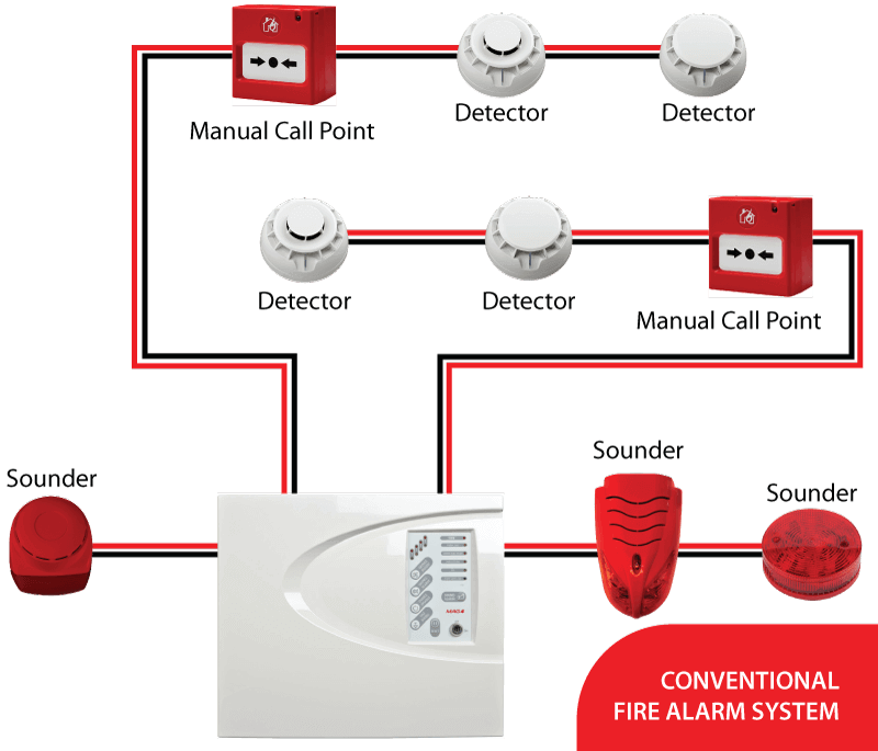
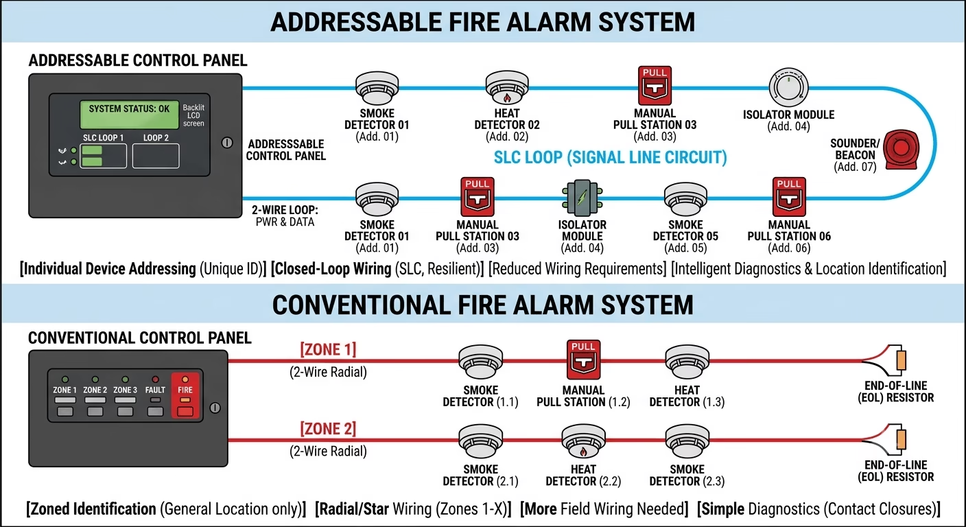
In a conventional system, detectors and manual call points are wired back to the control panel in groups called zones. Each zone typically covers a floor, a section of a building, or a defined area. When a device activates, the panel identifies which zone has triggered — but not which specific device within that zone.
Think of it like a circuit breaker panel. If a breaker trips, you know which circuit is affected — but not exactly which outlet caused the problem. You still have to walk the zone and investigate manually.
Wiring Topology
Conventional systems typically use a radial (star) wiring topology. Each zone runs a dedicated cable from the panel to a series of devices on that circuit. End-of-line (EOL) resistors are fitted at the last device on each zone to allow the panel to supervise the circuit for open or short-circuit faults.
Typical cable specification: 1.5mm² fire-rated LSZH (Low Smoke Zero Halogen) screened cable, installed to BS 5839-1 requirements.
Where Conventional Systems Work Well
- Small offices, retail units, or single-floor buildings (under 300m² per zone)
- Straightforward projects with a limited number of zones (typically under 10 zones)
- Budget-constrained installations where simplicity and lower panel cost is a priority
- Temporary or modular structures
| Field Note
I have seen conventional systems installed in buildings that clearly needed addressable systems — just to save on panel cost. The result was always the same: a fault develops, the entire zone goes offline, and the maintenance team spends hours isolating the faulty device instead of minutes. |
Addressable Fire Alarm Systems
How It Works
Addressable systems give every single device on the network a unique address — a digital identity. When a detector activates or develops a fault, the panel does not just tell you which zone. It tells you exactly which device, its location, and its status.
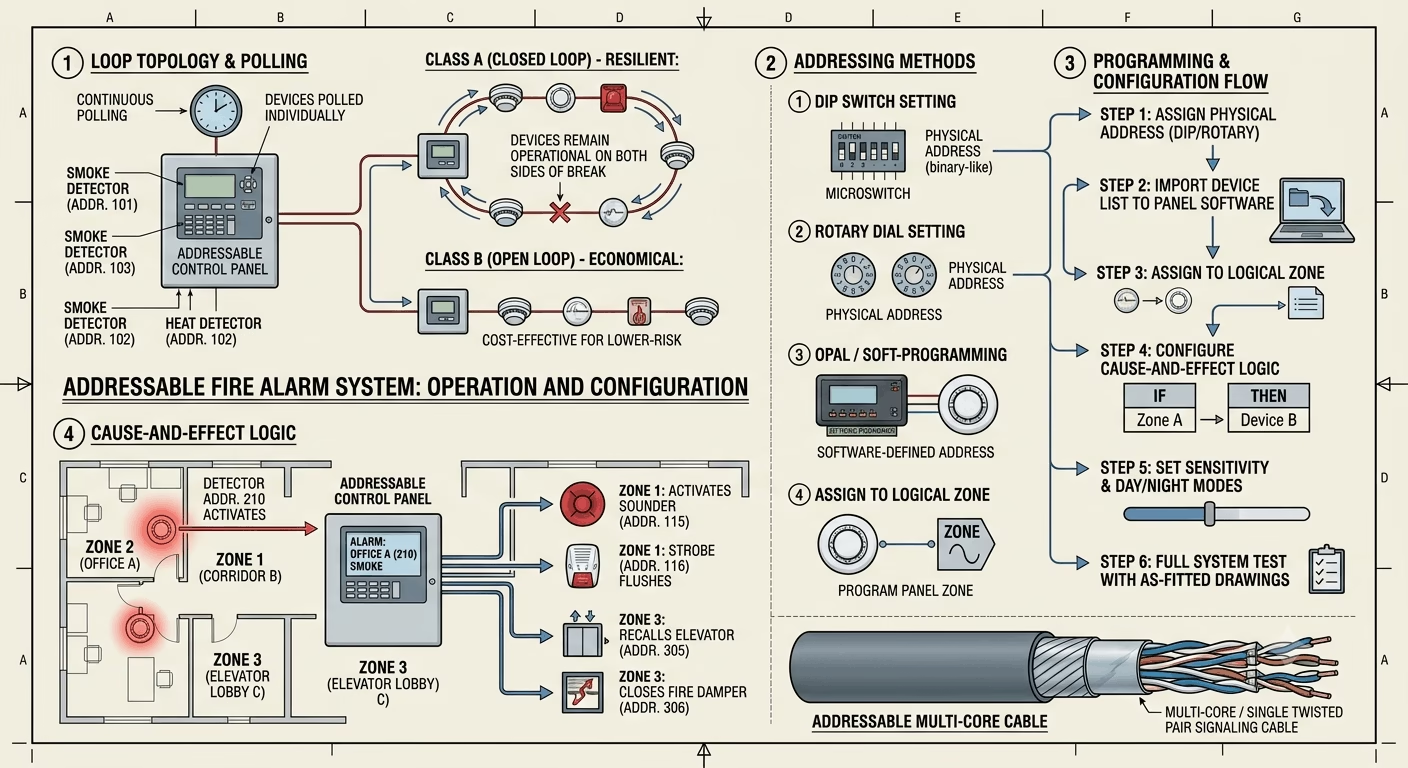
Most addressable panels use a SRL (Single-ended Resistive Loop) or DRL (Dual-ended Resistive Loop) topology. Devices are connected in a loop — sometimes called a signalling line circuit (SLC) in NFPA 72 terminology. The panel polls each device continuously, typically multiple times per second. (Read More)
Wiring Topology
The most resilient configuration is a Class A (Style D/E/F in NFPA 72, or Type A in BS 5839) closed loop. This means the loop cable leaves the panel, connects all devices, and returns to the panel from the other direction. If the cable is cut at any single point, devices on both sides of the break remain operational.
In practice, many installations use Class B (Style B/4 in NFPA 72) open-end loops for cost saving — which is acceptable for lower-risk occupancies but should always be discussed with the fire authority during design.
Programming and Configuration
Addressable systems require panel programming — this is where many engineers feel less confident, but it is not as complex as it looks once you understand the structure. Every panel brand has its own software tool (Hochiki’s HFP, Notifier’s ONYX, Siemens Sinteso, etc.), but the logic is always the same:
- Assign a physical address to each device (using DIP switches, rotary dials, or OPAL tools)
- Import the device list into the panel configuration software
- Assign each device to a logical zone
- Configure cause-and-effect logic (e.g., Zone 1 detector activates → Zone 2 sounder, close fire damper relay, elevator recall)
- Set sensitivity levels, coincidence settings, and day/night mode where required
- Run full test with as-fitted drawings
| Pro Tip
Always keep a backup copy of the panel configuration file (typically .cfg or .prj format) on your laptop and on the handover USB. A corrupt panel database is one of the most painful faults to diagnose months after commissioning. |
Head-to-Head Comparison
Here is a direct side-by-side comparison to help you evaluate which system fits your project:
| Feature | Conventional System | Addressable System |
| Detection Granularity | Zone-level only | Device-level (exact point) |
| Wiring | Multiple zone cables | Single loop (SRL/DRL) |
| Fault Location | Entire zone goes offline | Exact device identified |
| Cost (Initial) | Lower | Higher |
| Cost (Maintenance) | Higher long-term | Lower long-term |
| Scalability | Limited | Highly scalable |
| Suitable For | Small/simple buildings | Large/complex facilities |
| Standards Compliance | BS 5839, NFPA 72 | BS 5839, EN 54, NFPA 72 |
| Programming Required | None | Yes (panel software) |
Applicable Standards — BS 5839 vs. NFPA 72
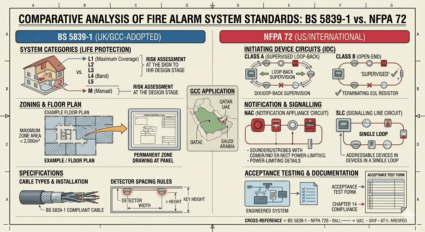
Both BS 5839-1 (UK/GCC-adopted) and NFPA 72 (US/international) govern the design, installation, and maintenance of fire alarm systems. Understanding which standard applies to your project is critical — and in the GCC region, you will frequently encounter both on the same project depending on the client’s preference and the local Civil Defence authority.
BS 5839-1 — Key Points for System Design
- Defines Categories L1–L5 (Life Protection) and M (Manual) systems — L1 provides maximum coverage throughout the building
- Requires a risk assessment to determine appropriate category before design begins
- Specifies maximum zone areas (not exceeding 2,000m² per zone) and maximum floor coverage per zone
- Requires a floor plan zone drawing to be permanently displayed at the panel
- Specifies cable types, installation heights for detectors, and spacing rules
NFPA 72 — Key Points for System Design
- Uses Initiating Device Circuit (IDC) classifications — Class A (supervised loop-back) or Class B (open-end)
- Notification Appliance Circuit (NAC) design governs sounder/strobe wiring
- Defines Signalling Line Circuit (SLC) for addressable systems
- Requires Acceptance Testing per Chapter 14, with formal documentation
- Referenced widely in Qatar, UAE, Saudi Arabia alongside local Civil Defence codes
| GCC Guidance
In Saudi Arabia, the Saudi Building Code (SBC 801) and Civil Defence requirements align closely with NFPA 72. However, many hospital and airport projects in KSA also specify BS 5839. Always confirm the applicable standard with the consultant and local Civil Defence office at the design stage — not after installation. |
Step-by-Step: Designing a Fire Alarm System
Whether you are designing a conventional or addressable system, the workflow follows the same logical progression. Here is how I approach it on every project:
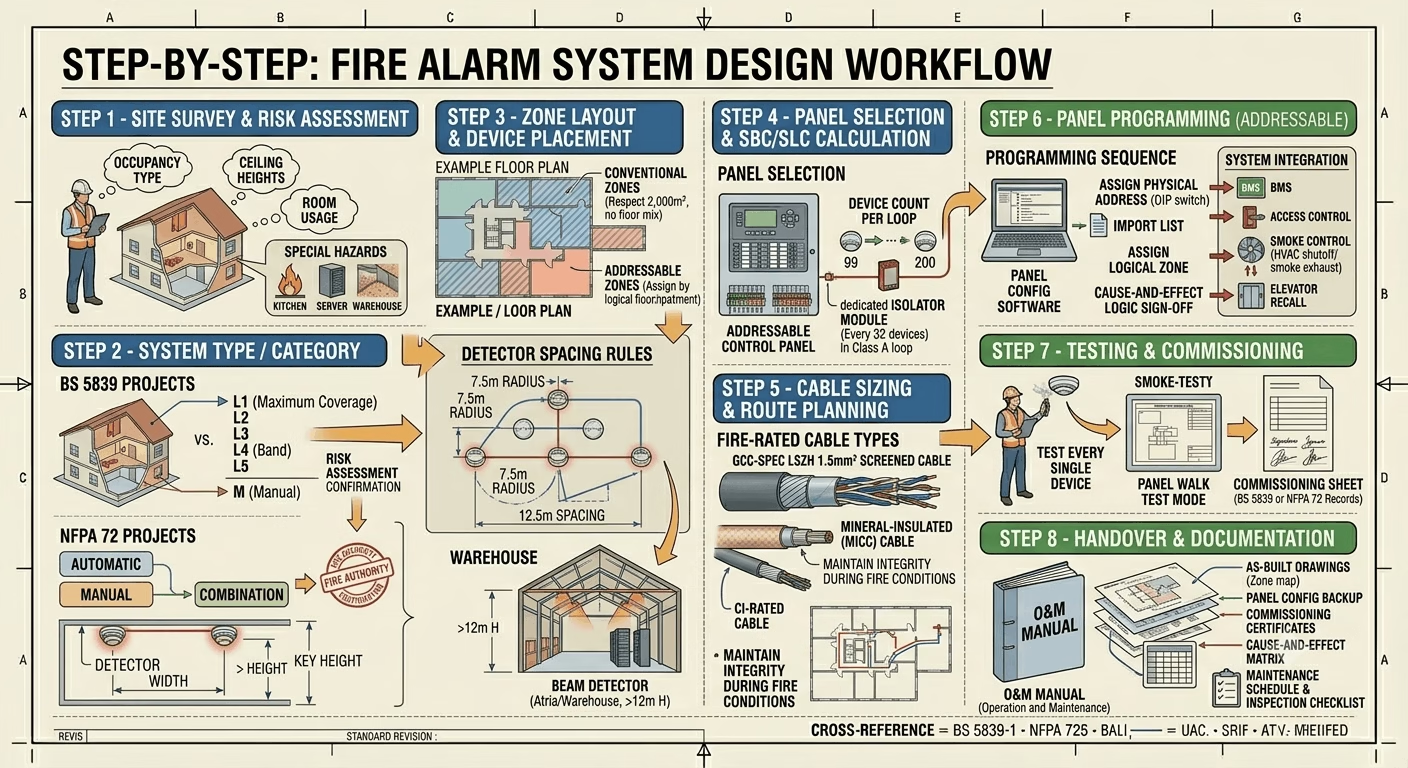
Step 1 — Site Survey and Risk Assessment
Before you open a single drawing, walk the site. Identify occupancy type (residential, commercial, industrial, healthcare), ceiling heights, room usage, and any special hazards — kitchen areas, server rooms, atria, or high-dust environments. This determines detector type selection and spacing.
Step 2 — Determine the Required Category / System Type
For BS 5839 projects: define Category L1 through L5 based on the risk assessment. For NFPA 72 projects: determine if an automatic system, manual system, or combination is required. Confirm with the fire authority if required — especially for hospitals, high-rises, and assembly occupancies.
Step 3 — Zone Layout and Device Placement
Map out zones on floor plans. For conventional systems, respect the 2,000m² per zone limit (BS 5839) and do not mix floors in the same zone. For addressable systems, assign logical zones that make operational sense — typically one zone per floor or one zone per fire compartment.
Detector spacing rules (typical for point smoke detectors in standard ceiling height up to 6m):
- Horizontal coverage: 7.5m radius from detector center (covers approximately 100m² per detector)
- Maximum spacing: 12.5m between detectors on flat ceilings under 3.5m height
- Beam detectors: suitable for atriums, warehouses, open spaces above 12m ceiling
Step 4 — Panel Selection and SBC/SLC Calculation
Choose a panel with sufficient loop capacity. For addressable systems, calculate total device count per loop. Most modern panels support 99 to 200 devices per loop. Use dedicated isolator modules at regular intervals (typically every 32 devices) on Class A loops to limit fault propagation.
Step 5 — Cable Sizing and Route Planning
Fire alarm cables must be fire rated. In most GCC projects, LSZH (Low Smoke Zero Halogen) 1.5mm² screened cable is specified. For high-risk or smoke-ventilated environments, mineral-insulated (MICC) or CI-rated cables are required to maintain circuit integrity during fire conditions.
Step 6 — Panel Programming (Addressable Systems)
Follow the programming sequence outlined earlier in this article. Ensure cause-and-effect logic is reviewed and signed off by the consultant before testing. Integrate with BMS, access control, smoke control (HVAC shutdown/smoke exhaust activation), and elevator recall per project specifications.
Step 7 — Testing and Commissioning
Test every single detector and manual call point — no exceptions. Use the panel’s walk test mode to avoid triggering the full alarm during device-by-device testing. Document results on commissioning sheets signed by the engineer and witnessed by the client or consultant representative.
Step 8 — Handover and Documentation
Compile the full O&M (Operation and Maintenance) manual including:
- As-built drawings with device locations and zone maps
- Panel configuration file backup
- Commissioning test certificates (BS 5839-1 Clause 57 or NFPA 72 Chapter 14 records)
- Cause-and-effect matrix
- Maintenance schedule and weekly/monthly/annual inspection checklist
Integration with Other Building Systems
Modern fire alarm systems rarely operate in isolation. On any medium to large project, you will be coordinating interfaces between fire alarm and other building systems. Here are the most common integrations I handle:
BMS (Building Management System)
Fire alarm panels typically provide dry contact relay outputs or BACnet/Modbus protocol interfaces to BMS. Common outputs include fire alarm active, fault status, zone-by-zone status. The BMS uses these signals for HVAC shutdown, pressurization activation, and central monitoring.
Access Control
Door hold-opens (magnetic locks) must be released on fire alarm activation. This requires either a direct relay interface or a networked integration between the fire alarm and access control panel. Fail-safe lock specification is critical — confirm with the fire authority that all fire escape routes use fail-safe (power-to-lock) hardware.
CCTV
Alarm-triggered CCTV recording or camera pop-up on the VMS workstation is increasingly specified on large sites. This gives the security team visual confirmation of an activation before deciding to evacuate or investigate. Most IP-based VMS platforms support fire alarm event triggers via dry contact or API.
Voice Evacuation / PA System
On complex buildings, the fire alarm panel interfaces with the PAVA (Public Address and Voice Alarm) system. Zoned voice evacuation — where only the fire floor and floors immediately above and below are initially announced — is standard for high-rises. This requires careful cause-and-effect programming between the fire alarm and PAVA controller.
Common Mistakes to Avoid
After commissioning dozens of fire alarm systems, these are the errors I see repeatedly — and they are all avoidable:
- Mixing floors in the same zone on a conventional system — a violation of BS 5839-1 and operationally useless during an actual fire
- Installing smoke detectors in high-dust environments without specifying dust-rated or aspirating detectors — guarantees chronic false alarms
- No isolator modules on addressable loops — a single wiring fault can take down the entire loop
- Failing to update the panel configuration after on-site changes — as-built drawings must match actual installation
- Skipping the cause-and-effect review — discovering that the fire alarm triggers all access control doors open (instead of just fire escape doors) during witness testing is embarrassing and costly to fix
- Under-specifying cable — using standard NYY cable instead of fire-rated LSZH or MICC defeats the entire purpose of circuit integrity requirements
Conclusion
Addressable and conventional fire alarm systems both have their place — but making the right choice requires understanding your building, your risk profile, and the lifecycle of the system you are installing. Conventional systems are cost-effective and simple for small buildings. Addressable systems pay back their higher initial cost on any project where fast fault diagnosis, precise alarm location, and integration with other building systems matter.
If there is one principle I would leave you with from years in the field: design for the maintenance engineer, not just the installation engineer. The person who has to trace a fault at 2am in an occupied hospital will thank you for choosing addressable, getting the loop design right, and keeping the commissioning documentation up to date.
Got a fire alarm project question or a specific panel integration challenge? Drop a comment on techubox.com or reach out directly — real-world questions get real-world answers.
About the Author
Sarwar is a Technical Project Engineer at Norden Communication with over 15 years of hands-on field experience in ELV and security systems, including fire alarm, CCTV, access control, PA/voice evacuation, and fiber optics. He supports distributors through project installation, configuration, and formal handover across the GCC region. He also runs techubox.com, a technical blog for security and ELV engineering professionals.