Solar Electrical Power System
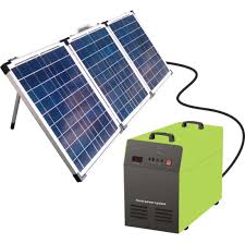
A solar power system, commonly referred to as a photovoltaic (PV) system, is a device that effectively converts sunlight into electrical energy.
Fundamentals of Electricity
Electricity is a form of energy resulting from the flow of electric charge three most basic components of electricity are voltage, current, and resistance
Voltage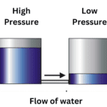
It measures the electric potential energy per unit charge between two points in an electrical circuit. Voltage is measured in volts (V) & referred to as “electrical pressure.” It has a polarity, indicating a voltage source’s positive and negative terminals.
Current Or Ampere
The ampere is defined as one coulomb of electric charge passing through a given point in one second. Electric current is the flow of electric charge in a circuit, and the ampere is used to measure the intensity or magnitude of this current. The scientific symbol is “I” and for the “intensity” of the current, the electrical symbol is “A”,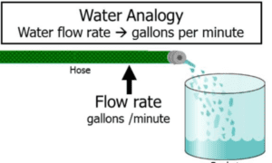
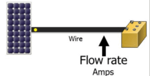
In a water analogy, water flow is measured in gallons per minute. The rate at which electrons flow through a conductor is measured in amps, which is the unit for current.
Resistance
Resistance refers to the capability of a material to resist the flow of an electrical current, similar to how friction slows down the flow of water through a pipe. The symbol omega (Ω) or the letter R represents and measures electrical resistance in ohms.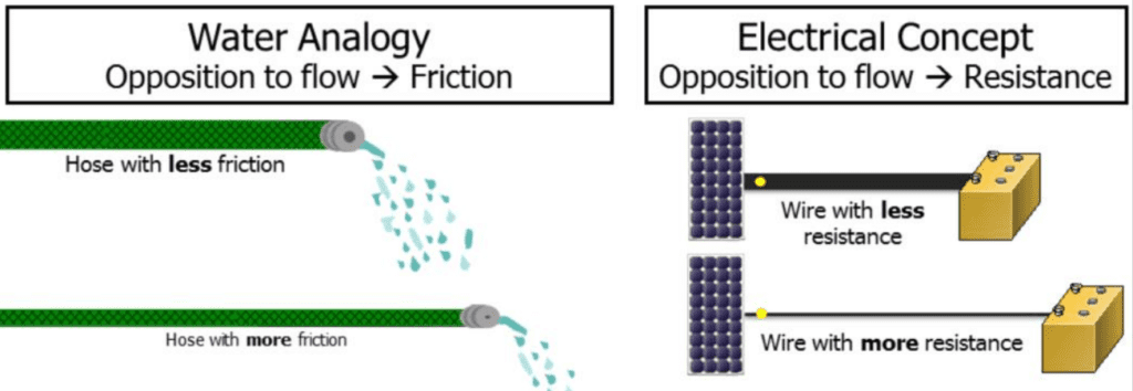
In the water analogy, the resistance or friction of a hose determines the flow of water. Higher resistance leads to reduced water flow. Factors influencing the friction in the hose include its length, material, cross-sectional area (thickness), and temperature.
Conductor resistance depends on:
Material: Copper is more conductive but expensive.
Area: A larger cross-sectional area reduces resistance.
Length: Longer conductors have higher resistance.
Temperature: Higher temperatures increase resistance. Electrons flow through the path with the least resistance. If resistance is too high or no path exists, the current won’t flow.
Types of Electrical Current
Direct Current (DC)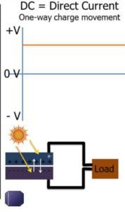 : Direct current is the flow of electric charge in a constant direction. In a DC circuit, the electric current maintains a consistent polarity, with electrons flowing from the negative terminal to the positive terminal. Batteries and solar cells are common sources of direct current. Photovoltaic (PV) panels produce a type of current known as direct current (DC).
Alternating Current (AC):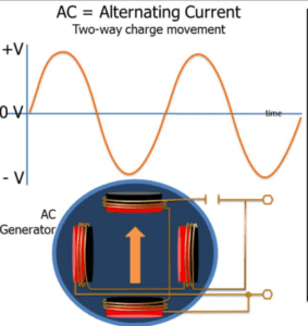 Alternating current periodically changes direction. The flow of electric charge in an AC circuit reverses at regular intervals, typically in a sinusoidal waveform. The voltage starts at zero, rises to its peak, and falls back to zero. This sine wave curve represents one cycle per second or one Hertz. It does all this 50 or 60 times a second.
Watts or Power
Electricity is measured in watts (W), which is the product of voltage (V) and current (A). In other words, W = V x A.
Power refers to the energy being used or produced at a given moment.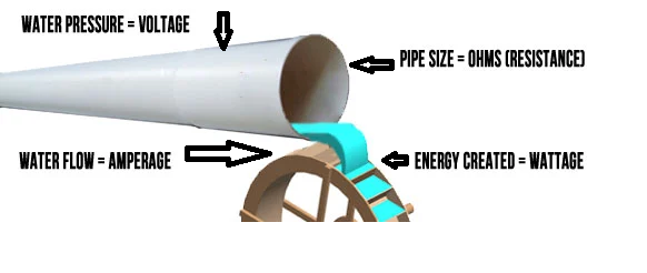
Power is the rate at which energy is consumed or transferred. It represents how quickly work is done or how quickly energy is used. In the context of electricity, power is measured in watts (W).
Voltage, measured in volts (V), represents the electrical potential difference or the pressure that drives electric current. It can be thought of as the force that pushes electrons through a circuit. Different devices and systems require specific voltage levels to operate correctly.
Current, measured in amperes or amps (A), refers to the flow of electric charge in a circuit. It represents the quantity of electric charge passing through a given point per unit of time. Voltage and resistance determine the electric current in a circuit.
The equation expressing the relationship between power (P), voltage (V), and current (I) is P = V x I.
P = V x I
This equation demonstrates that power (in watts) is equal to the product of voltage (in volts) and current (in amps).
What will be the power rating of the above solar module array?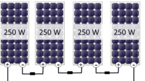
- it will be =250×4 modules,
- =1000watt
- =1kW
- The DC size of the PV array should be measured either in watts or kilowatts. This is the most common and reliable method to determine the system’s capacity.
Examples:
How many amps does a 100-watt, 220-volt light bulb use?
A = W ÷ V
= 100 W ÷ 220 V
= 0.45 A
How many watts does a 10-amp, 30-volt PV module produce?
W = V x A
= 30 V x 10 A
= 300 W
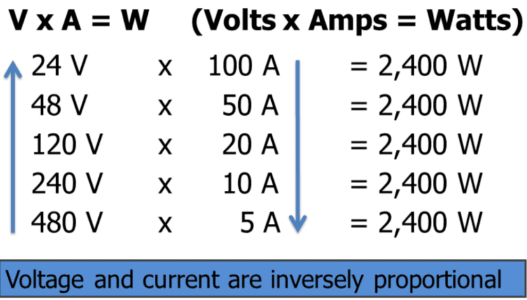
A 2,400-watt solar panel array produces 100 amps of current when operating at 24 volts. However, if the voltage is doubled to 48 volts, the current output is halved to 50 amps. When the voltage is increased to 120 volts, the array produces only 20 amps of current. As the voltage continues to increase, the current output decreases; at 240 volts, the current is 10 amps, and at 480 volts, it is just 5 amps.
kilowatt-hours (kWh)
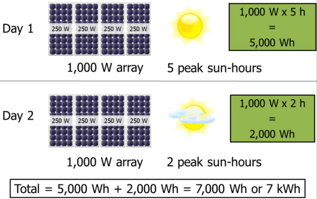
Watts is the measurement we use to describe power. But when it comes to measuring energy, we need to consider both the amount of power and the duration for which it is used. That’s why we use units like watt-hours (Wh) or kilowatt-hours (kWh). These units tell us how much power, in watts, is being produced or consumed over a specific period, usually in hours. To calculate energy, we simply multiply the power in watts by the duration in hours, and the result is expressed in watt-hours.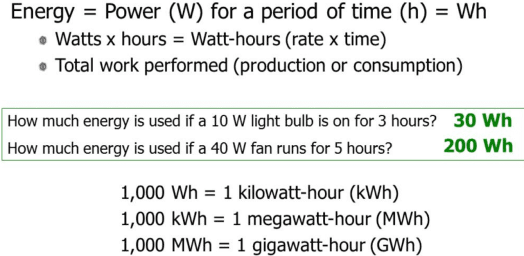
How much energy will be produced with the following array?
Designing of a Solar electrical system
- Solar Panel Connection in Series.
- Solar Panel Connection in Parallel.
- Solar Panel Connection in Series & Parallel.
- Battery Bank Connection in Series, Parallel, and Both.
Solar Panel Connection in Series
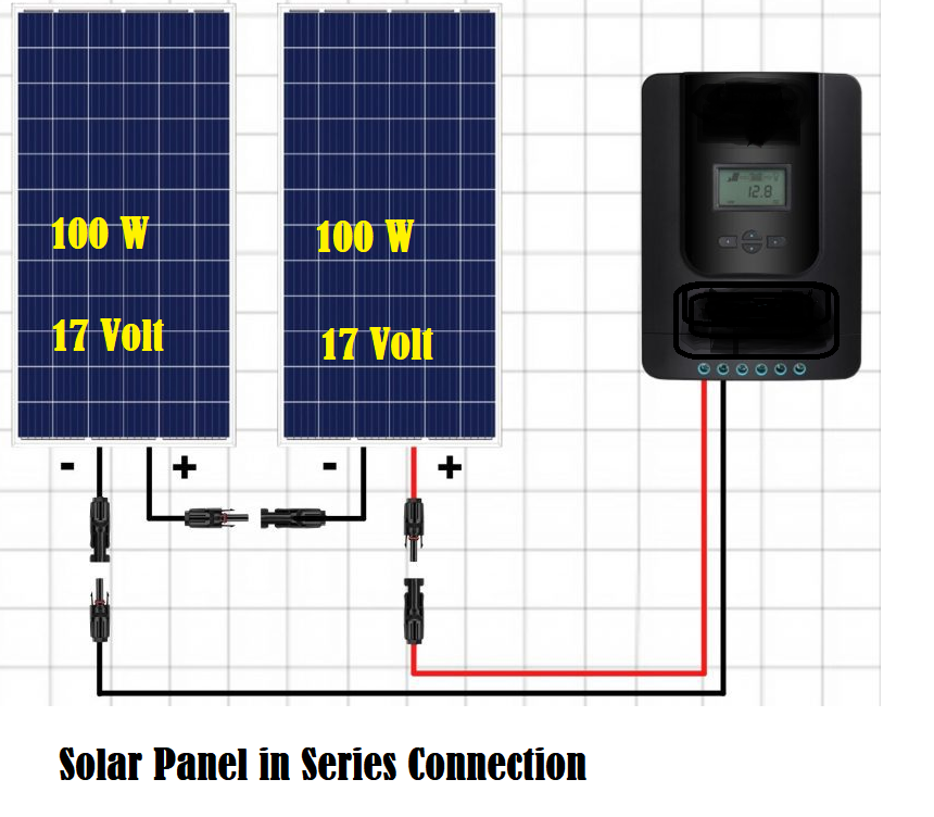
Eac h panel should be identical, or they should have the same current rating.
in a series of connections, “Connect the positive cable of the first solar panel to the negative cable of the second, and so on.
The total voltage of the above panel =17Volt+17Volt=34Volt DC
The total Current of the Above panel =5.88A (100/17V)
The Total Power of the above panel =34Volt x 5,88A=200 Watt
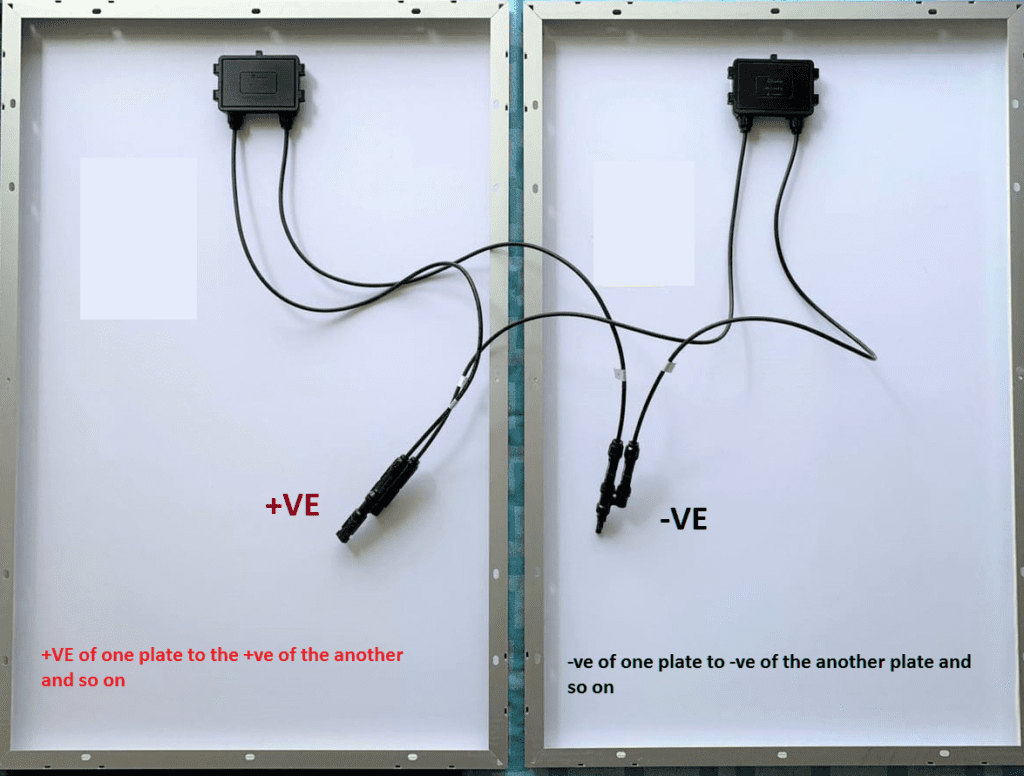
Solar Panel Connection in Parallel
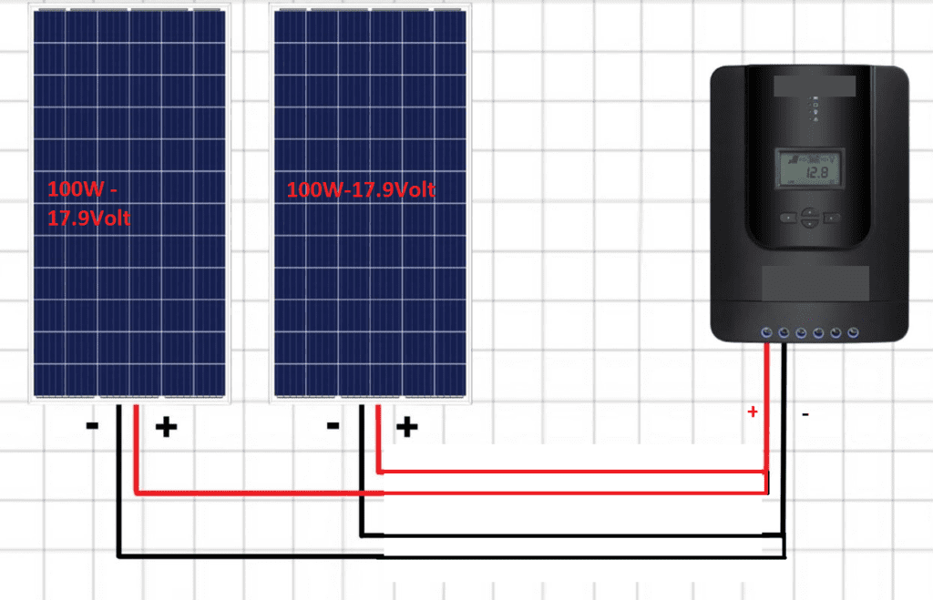
“Connect the positive cable of the first solar panel to the positive cable of the second, and so on. and the negative cable of the first solar panel to the negative of the second, and so on.
The total voltage of the above panel is 17.9 volts.
The total current of the above panel is 5.58A + 5.58A = 11.16A.
The total power of the above panel is 17.9 volts x 11.16 A = 200 watts.
When Should We Wire Solar Panels in Series and Parallel?
When wiring solar panels, you have two options: series and parallel configurations. The choice depends on your electrical requirements and desired outcome. Here’s a breakdown of when to use each:
Series Wiring:
To increase voltage output, wire solar panels in series by connecting one panel’s positive terminal to the next’s negative terminal. This adds up the voltage of each panel, providing a higher total output. It is useful for charging high-voltage battery banks or connecting to an inverter needing a higher input voltage.
Example: If you have three solar panels with an output voltage of 12 volts each, wiring them in series will result in a total voltage of 36 volts (12V + 12V + 12V).
Pros
- No additional parts or equipment are required.
- By keeping the current (amperage) low, you can use a smaller-gauge wire.
- “It works better in low light.”
Cons
- When a single panel in a series configuration is shaded, the power output of the entire array drops, making it ineffective under shade.
Parallel Wiring:
To increase the current output from your solar panels, connect all panels’ positive and negative terminals in parallel. This will combine the currents from each panel and increase the overall production. Use parallel wiring when you must match a specific current requirement, such as charging a battery bank faster or connecting to an inverter requiring a higher input current.
Example: If you have three solar panels with an output current of 5 amps each, wiring them in parallel will result in a total current of 15 amps (5A + 5A + 5A).
Pros
- When a panel in a parallel configuration is shaded, the remaining panels will continue outputting power.
- Solar panels in parallel perform better in mixed-light conditions than in series.
Cons
- Requires connectors.
- A circuit protection fuse is needed.
- Thicker wire and higher-amp-rated equipment are needed to handle high currents.
- It doesn’t work as well in low light.
Solar Panel Connection in Series & Parallel
Series Connection:
Connecting solar panels in series means connecting the positive terminal of one panel to the negative terminal of the next panel. This configuration increases the total voltage output while keeping the current constant.
The voltage of each panel adds up, while the current remains the same. For example, if you connect two 12-volt panels in series, the total voltage output will be 24 volts (12 volts + 12 volts). Series connections are useful when you need to increase the voltage output.
Parallel Connection:
This configuration increases the total current output while keeping the voltage constant. All the positive terminals will be connected to the positive, and all the negative terminals will be connected to the negative.
Parallel connections are useful when you need to increase the current output to power devices or charge batteries that require a higher current.
Series-Parallel Combination:
To achieve both a higher voltage and a higher current output, a combination of series and parallel connections can be used. Multiple sets of panels can be connected in series, and then these sets can be connected in parallel.
The series-parallel combination provides flexibility in meeting both voltage and current requirements.
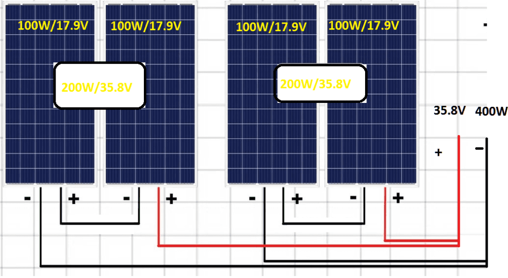
The above example shows four solar modules connected in series and parallel
In a series connection, the voltage and wattage of each array will be added (module + module), and the ampere will be the same.
In a parallel connection, Ampere & wattages will be added, and voltage will be the same
Total Voltage: 35.8V.
Total Amp: (5.59+ 5.59) = 11.18A.
Total Power (watts): 11.18Ax35.8V=400W.
Solar Panel Connection in Series & Parallel with Different Values
When connecting solar panels in series or parallel with different values, it’s important to consider the voltage, current, and power characteristics of the panels
Series Connection with Different Values:
When connecting solar panels with different voltage or current ratings in series, the total voltage will be the sum of the individual panel voltages, while the current remains the same as the panel with the lowest current rating.
For example
Panel 1: 12 volts, 5 amps
Panel 2: 24 volts, 3 amps
The total voltage will be 36 volts.
The total current will be 3 amps (the lowest one).
The lowest-rated panel (Volt/Amp) limits the full series-connected panel’s performance.
Parallel Connection with Different Values
When connecting solar panels with different voltage or current ratings in parallel, the total current will be the sum of the individual panel currents, while the voltage remains the same as the panel with the lowest voltage rating.
For example
Panel 1: 12 volts, 5 amps
Panel 2: 24 volts, 3 amps
The total voltage will be 12 volts. (the lowest one)
The total current will be 5+ 3 = 8 amps.
The lowest-rated panel (Volt/Amp) limits the full parallel-connected panel’s performance.
Series-Parallel Combination with Different Values
If you have multiple solar panels with different values and want to achieve both a higher voltage and a higher current output, you can use a combination of series and parallel connections.
Let’s consider the following example with three panels: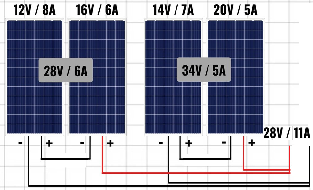
Battery Bank Connection in Series, Parallel, and Both
continue………….