Introduce:
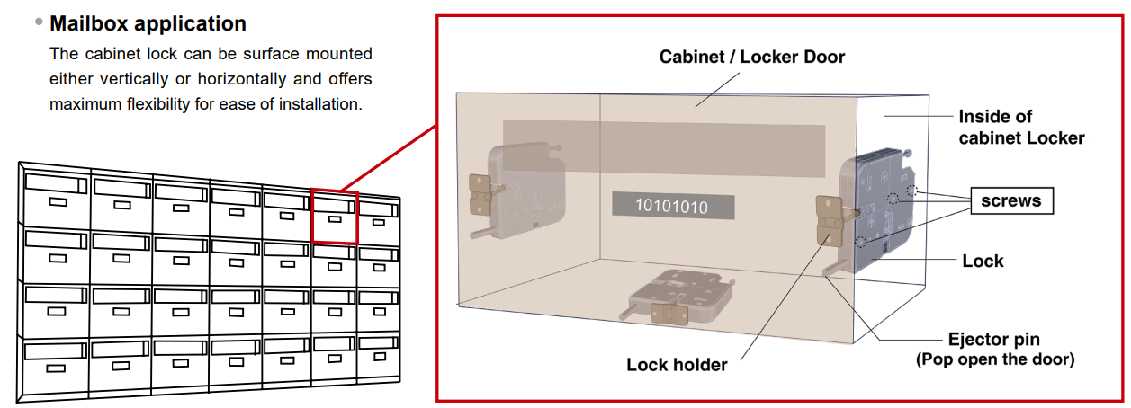
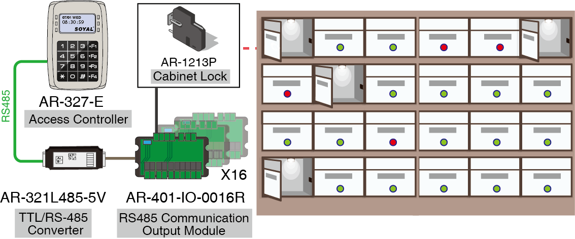
The AR-1213P locker is designed to provide a reliable and secure storage solution for various items. It offers integration capabilities with electronic mailboxes or parcel lockers, which can be achieved using the E series controller and RS485 communication module (AR-401-IO-0016R).
This integration allows for seamless communication between the AR-1213P locker and the electronic mailbox or parcel locker system, enabling efficient and convenient management of stored items. With support for up to 256 units, it offers scalability and flexibility to accommodate different storage needs.
In addition to its integration capabilities, the AR-1213P locker can be further enhanced by pairing it with a voice module. This voice module enables the locker to provide voice prompts, which can be helpful for users in guiding them through the storage process. Whether providing instructions on how to use the locker or notifying users about the status of their stored items, the voice prompts add an intuitive and user-friendly touch to the overall experience.
Overall, the AR-1213P locker with its integration options and voice module features combines convenience, security, and user-friendliness to deliver an enhanced storage solution
HARDWARE REQUIREMENTS
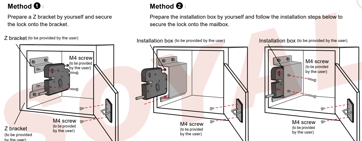
- AR1213P(Cabinet Lock)
- Access Controller(AR327-E)
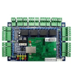
- AR-401-io-0016R(Elevator Controller)
- AR-321L485-5V (Media Converter)
- Software client /server
- Lockers
Setting precautions:
To prevent any potential damage and excessive heating of the coil, it is essential to ensure that the electric lock time of the controller is set to a value below 0.5 seconds. This precautionary measure helps to avoid continuous triggering of the power switch over extended periods. By selecting the lock time within this specified range, you can maintain the optimal functioning and longevity of the system without risking any potential harm.
E-series screen access controller:
process of configuring the settings for the desired card-swiping waiting and relay time range. Here are the steps and options explained in more detail:
To begin, enter the editing mode by using the default value *123456#.
Once in the editing mode, navigate to the Tools menu. This menu provides access to various configuration options.
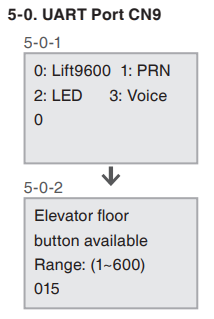
UART Port CN9: Within the Tools menu, select option 5 or the corresponding option for UART Port CN9. This option allows you to configure the settings related to the card-swiping waiting time range.
Lift9600: Once inside the UART Port CN9 settings, set it to 0 for Lift9600. This selection enables you to adjust the card-swiping waiting time.
Card-Swiping Waiting Time Range: The card-swiping waiting time range determines the duration the system waits for a card swipe to be detected. The exact content of available waiting times may vary depending on the specific device or system. Adjusting this waiting time range allows you to fine-tune the system’s responsiveness to card swipes.
Relay Time: The relay time refers to the duration for which an electrical relay remains activated. Here are the available options for setting the relay time:
Continuous Output Switching Mode: If you set the relay time to 000, the system will operate in continuous output switching mode. This means the relay will remain activated constantly until instructed otherwise.
Specific Time Durations: For values ranging from 001 to 600, you can set the relay time to a specific duration in seconds, ranging from 1 second to 600 seconds. This allows you to control how long the relay remains activated before automatically deactivating.
Precise Timing: If you require more precise timing, you can choose values from 601 to 609. These values represent a range of 0.1 second to 0.9 second. This level of granularity enables you to achieve shorter durations for the relay’s activation.
Enter editing mode (default value *123456#) > 5. Tools > 0. UART Port CN9 > 0: Lift9600 > Set card-swiping waiting time range.
E-Series touch-type Access controller:
To set the relay time for the floor control action, follow these steps:
Enter the edit mode by using the default value 123456#.
To set the relay time, use the command format 23MMMTTT#. Replace MMM with the Node ID of the lift controller, and TTT with the desired relay time.
For continuous output switching mode, use 000. This means the relay will stay activated until instructed otherwise.
To set a specific duration, choose a value between 001 and 600, corresponding to a range of 1 second to 600 seconds. This allows you to control how long the relay stays activated before automatically deactivating.
For more precise timing, select a value between 601 and 609. These values represent a range of 0.1 second to 0.9 second. This level of granularity enables you to set shorter durations for the relay’s activation.
MMM=Node ID of the lift controller
TTT=relay time
000 = Continuous output switching mode
001~ 600 = 1 second ~ 600 seconds
601~ 609 = 0.1 second ~ 0.9 second.
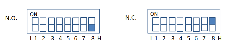
RS485 communication output module 401-IO-0016R dial setting:
The BAUD9600, N.C. TYPE elevator floor dedicated:
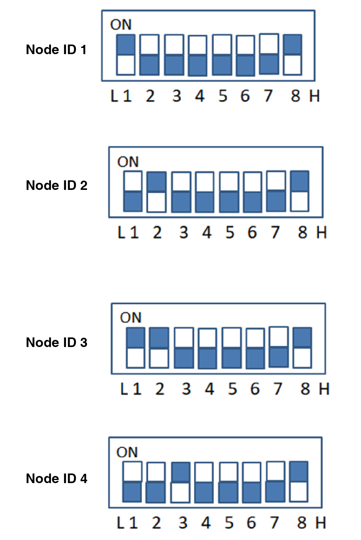
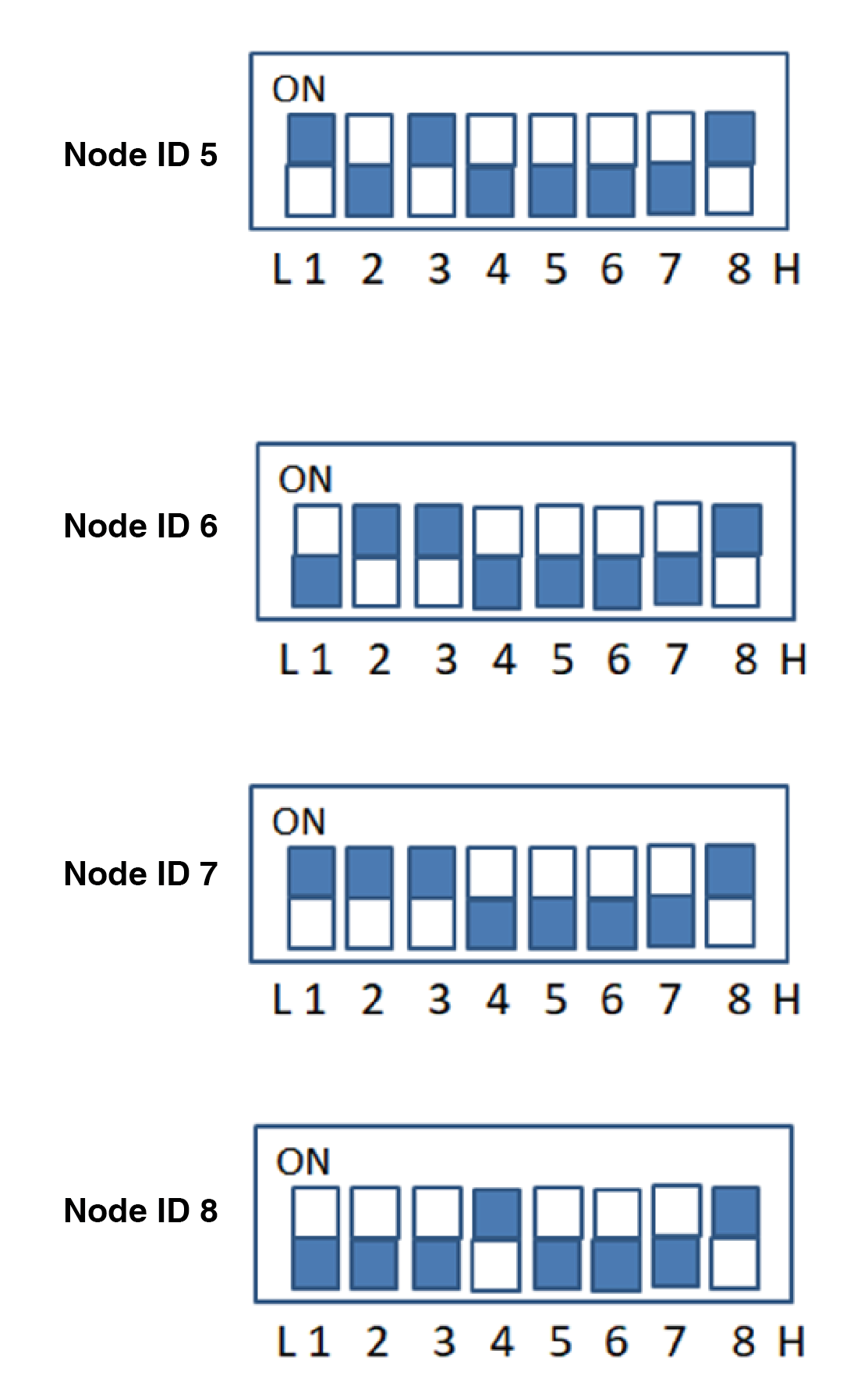
N.C./N.O. Type witch
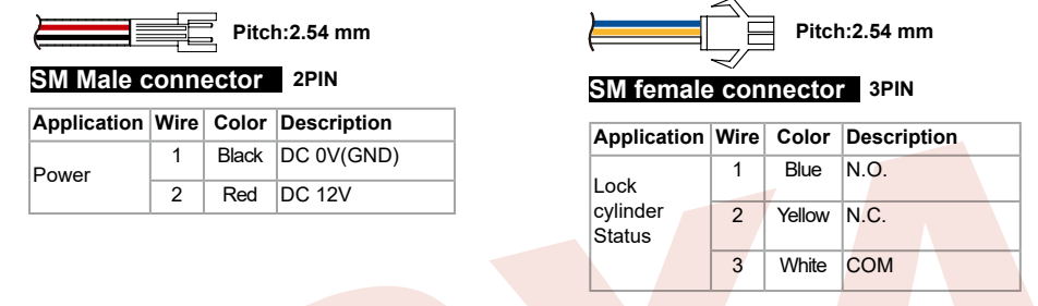
SW8: When the dial is set to OFF, it is in N.O. mode (used in mailboxes)N.O. Mode (Normally Open)
When the power is turned on, the device or equipment connected to it will be in the open state
SW8: When the dial is set to ON, it is in N.C. mode (used in elevators)N.C. Mode (Normally Closed)
When the power is turned on, the device or equipment connected to it will be in a closed state.
this article is designed and programmed in manual operation without Soyal Server & Client Software, the programming can be done easily by the software. Programming will be as like as elevator floor programming.