Mastering Fire Safety Device Placement and Spacing
This guide will particularly interest designers and installers who need simple guidance on fire device selection, spacing, and location.
SMOKE DETECTORS
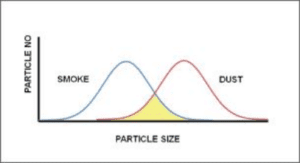
Smoke detectors need to be placed carefully, as large smoke particles can be similar in size to small contaminants like dust or aerosols. This could cause the detectors to mistake those particles for smoke and trigger unnecessarily. Proper placement is important to limit exposure to these non-smoke particles.
HEAT DETECTORS
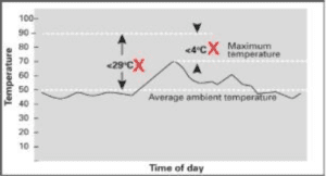
Heating devices must maintain a temperature at least 29 °C higher than the average surrounding air temperature, and withstand up to 4°C above their maximum expected operating temperature.
Fire detector coverage and positioning
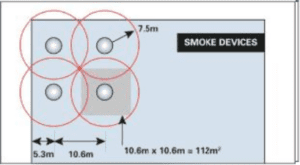
Smoke detectors are typically designed to effectively monitor an area with a radius of about 7.5 meters. However, to make sure there are no “blind spots” where smoke might go undetected, the coverage areas for individual smoke detectors need to overlap.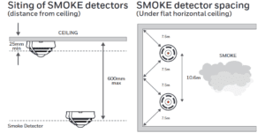 The actual coverage area for each smoke detector ends up being more like a square that measures 10.6 metres by 10.6 metres. This gives each detector an effective monitoring area of around 112 square metres. Each smoke detector must have a coverage area of at least 112 square meters, achieved by setting a 7.5-meter radius and overlapping detection zones to eliminate blind spots
The sensing element of a smoke detection device (photoelectric smoke chamber) should not be less than 25mm below the ceiling, and not greater than 600mm below the ceiling.
Heat Detectors
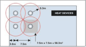
Heat detectors are designed to monitor an area with a radius of around 5.3 meters. But just like with smoke detectors, the coverage areas for individual heat detectors need to overlap to make sure there are no “blind spots” where a fire could go unnoticed.
Each heat detector has an actual coverage area of 56.3 square meters, represented by a 7.5 x 7.5 meter square, to account for the overlap of detection zones.
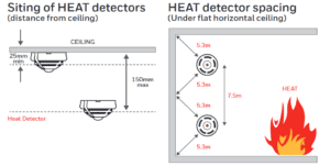
Each heat detector has a nominal 5.3-meter coverage radius, but the actual coverage area is 56.3 square meters (7.5 x 7.5 m) to ensure overlapping detection zones and complete coverage without blind spots, enabling reliable fire monitoring.
The sensing element of a heat detection device (thermistor) should not be less than 25mm below the ceiling, and not greater than 150mm below the ceiling
Corridors Spacing
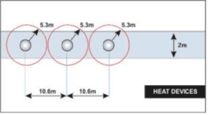
In corridors, less than 2 m wide, detector spacing can be increased, as overlapping coverage is not required. Corridors over 2 meters wide are treated as rooms, requiring standard detector spacing and overlapping coverage.
Detectors must be placed at least 1 meter away from air vents or HVAC equipment to avoid interference with their smoke and heat-sensing abilities.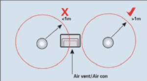
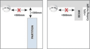 Detectors must be placed at least 500 mm away from any obstructions. If a solid partition is within 300 mm of the ceiling, it should be treated as a wall. Similarly, ceiling beams deeper than 10% of the ceiling height should also be considered walls when positioning detectors.
For ceilings with a pointed apex:
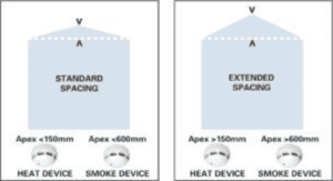
If the apex is less than 150 mm higher than the rest of the ceiling, you can treat it the same as a flat ceiling for heat detectors.
If the apex is less than 600 mm higher, you can treat it the same for smoke detectors.
If the apex is higher than those limits, you’ll need to install a detector at the very top of the apex.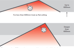
Also, if the ceiling has an angled slope (like a pitched roof), you can space the adjacent detectors slightly farther apart. The distance between them can be increased by 1% for every degree of angle, up to a maximum of 25% farther spacing.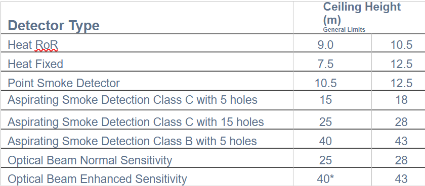
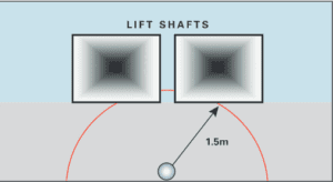
Vertical shafts, such as
elevator shafts and stairwells, should have a device installed within 1.5 meters of any opening.
Beam Detector Sitting
For ceiling-mounted beam detectors, the following general rules apply:
Coverage can be extended by 1% for each degree of angle up to a maximum of 25% on apex ceilings.
The maximum distance from the highest point should not exceed 600 mm. If this is not possible due to obstructions, the maximum distance from the ceiling should be less than 10% of th
e ceiling height, or 2.5 m.
Avoid positioning beams close (within 500 mm) to walls or where temporary obstructions may occur.
Transmitters and receivers must be mounted on a solid surface not affected by wind or temperature changes.
Additional detectors may be needed in atria to counter stratification effects, with the protected width on each side being 12.5% of the mounting height.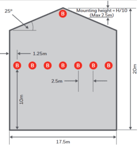
As an example, a single beam detector can cover an 18.75m span when using the maximum 25% extension allowed for the roof angle. The gap on either side of the detector should be 12.5% of the mounting height, which would be 1.25 m.

SEARCH DISTANCE
Individuals searching a zone for a fire must be able to identify the source within 60 meters of the zone’s entrance. Careful positioning of the detector’s LED is required to minimize the search distance. Zones should not cross floors.”.
Manual Call Point Placement
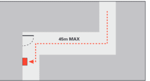
Along an escape route, the maximum travel distance to reach a manual call point should be no more than 45 meters. This distance is reduced to 25 meters if the route is intended for use by disabled persons or rapid fire development is likely. Manual call points must be located at all stairwells and building exits
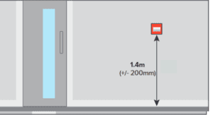
Manual call point elements should be centered 1.4 m (±200 mm) above the floor unless the location is intended for use by wheelchair users, in which case this should be noted in any certification. All manual call points must be fitted with a protective cover that must be moved to access the frangible element
Audible and Visual Alarm Device Guidelines

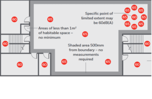
Audible alarm levels within buildings are generally accepted as 65dB(A) & in certain locations, this can be as low as 60 dB (A). The maximum sound level should not be greater than 120 dB (A) at any normally accessible point. Sounder volume may be reduced to 60 dB (A) in stairways,
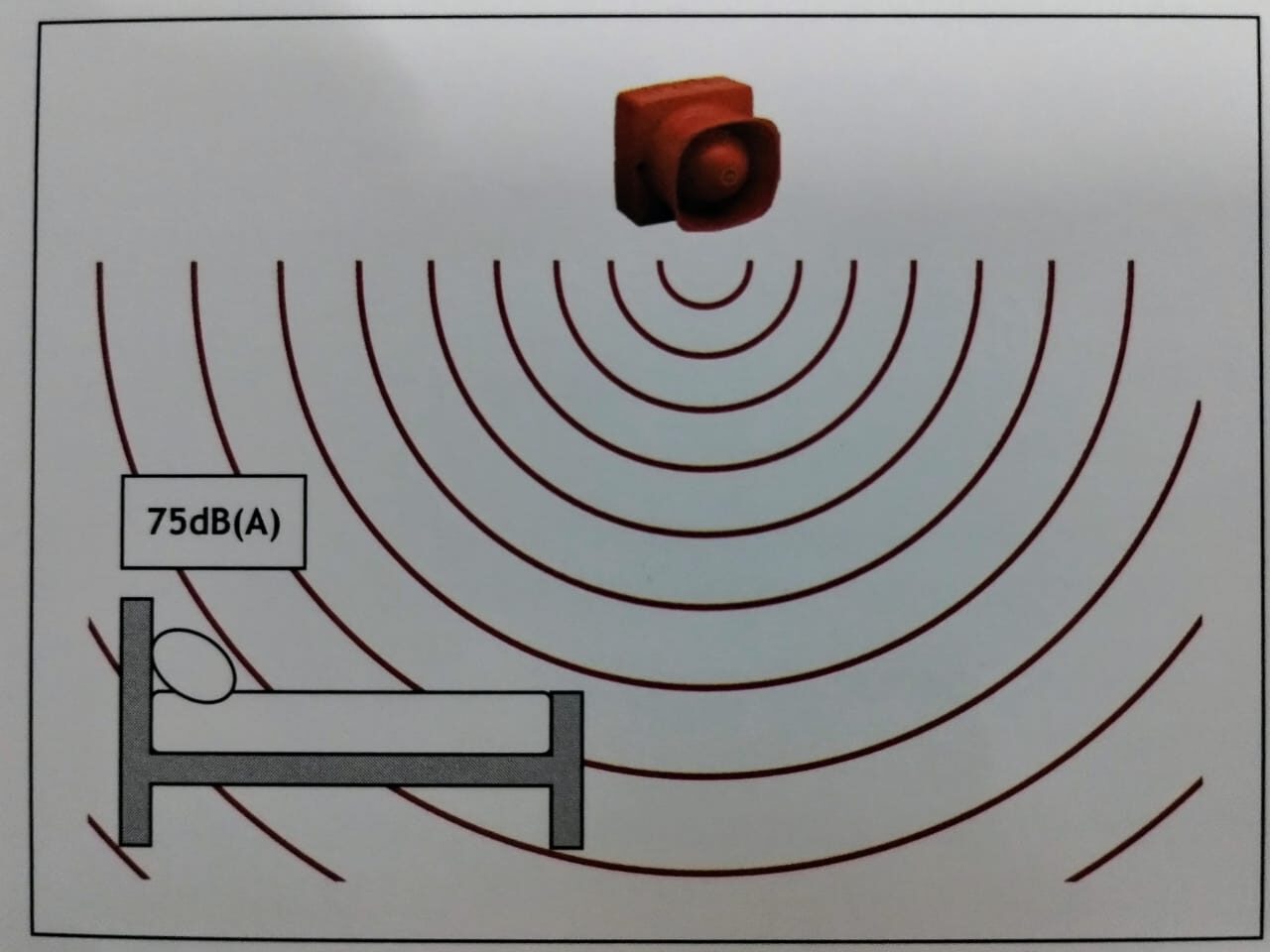
For areas where people are sleeping, sounder devices should produce a
minimum of 75dB(A) at the bed-head with all doors shut
Visual indication devices (VIDs), such as strobes, can be mounted on the ceiling or wall. When wall-mounted, they should be installed 2.1 meters above the floor.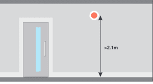
All cabling should be mechanically protected from floor level up to a height of 2m.
VADs are classified into three categories based on their application:
W: wall-mounted
C: Ceiling-mounted
O: Open Category
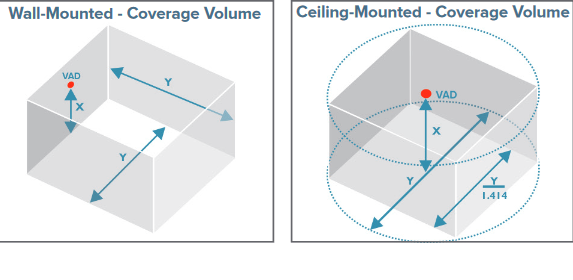
Wall-mounted visual alarm devices (VADs) cover a cuboid volume with a square floor area. The coverage volume is specified using a code in the format ‘W-X-Y’, where:
W indicates Wall-mounted
X is the maximum mounting height in metres
Y is the width and length in metres of the coverage floor area
The minimum mounting height for wall-mounted VADs is 2.4 metres
Ceiling-mounted visual alarm devices (VADs) cover a cylindrical volume. The coverage volume is specified using a code in the format ‘C-X-Y’, where:
C indicates Ceiling-mounted
X is the maximum mounting height in meters (3, 6, or 9 m)
Y is the diameter in meters of the coverage volume’s floor area
The maximum permitted mounting heights for ceiling-mounted VADs are 3, 6, or 9 meters
Cabling and Installation Best Practices
The core size should not be less than 1 mm, but 1.5mm at least.
• Where exposed cables are below 2 m, additional mechanical protection should be considered
• The color of the outer sheath should preferably be red, although other colors are permitted as long as it is common throughout the building and do not clash with any other electrical services
Fire cables should:
• be segregated from all other services.
• not share the same conduit.
• Use a separate compartment if common trucking is used.
• Avoid running alongside high-current power lines.
• Avoid running adjacent to lightning conductors.
• Avoid electromagnetic interference from other circuits.
Loop Length
The permitted loop length for Most Addressable Panels with 1.5mm2 cable is 2km, and this may be extended to 2.5k with 2.5mm2 cable. However, this length is dependent on the quantity and distribution of powered alarm devices.
Factors Affecting Loop Length:
Wire gauge and type: A larger gauge (thicker) wire can support longer loops.
Number of devices on the loop – More devices require shorter loops to maintain signal strength.
Loop configuration: Loops configured as Class A (redundant) can support longer lengths than Class B (non-redundant).
Power requirements: Devices that draw more current may limit loop length

